Hola Mundo en STM32
 Código base recién creado
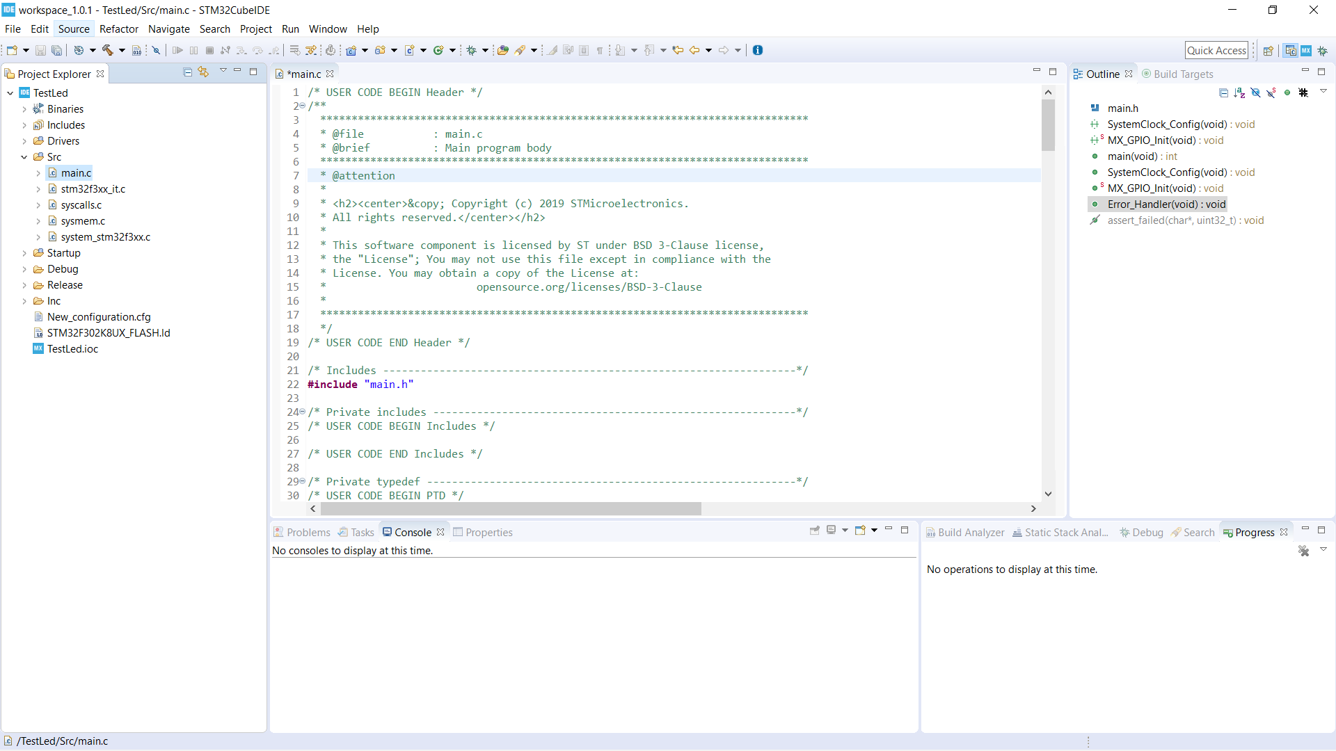
En éste paso, ya tendríamos que tener el código generado como hemos visto en IDE para STM32. El código se genera por defecto en src y Drivers de nuestro proyecto. Nuestro fichero principal es main.c que está dentro de src. Abrirlo y cambiar la perspectiva a C/C++. Veremos que en la nueva perspectiva, la interfaz ofrece un montón de ayudas y marcadores de texto que nos hará el trabajo mucho más productivo y fácil.
Antes de nada, nos tenemos que fijar en que CubeIDE nos genera a lo largo de todas las secciones, ficheros y librerías un montón de secciones encajadas entre títulos /* USER CODE BEGIN 0 */ y /* USER CODE END 0 */. Es en dichas secciones, y sólo en dichas secciones, donde programaremos. Si programamos fuera de dichas sencciones, CubeIDE no respetará nuestro código y lo borrará la próxima vez que regeneremos el código base, por ejemplo tras añadir una nueva interfaz o configurar nuevos pines. A veces, CubeIDE nos genera varias secciones seguidas de USER CODE en la misma sección y a la misma altura, es indiferente en cuál programemos, es sólo para nuestro orden. Se aconseja no borrar o modificar secciones de USER CODE independientemente de que no programemos en ellas.
Lo primero que siempre hago en todos mis programas es una serie de definiciones y añadir unas pequeñas funciones básicas que me ayudarán mucho a la hora de hacer los primeros programas y pruebas.
Definiciones básicas
Estas definiciones son sólo para CubeIDE y ayudarnos a la hora de programar. Al principio definiremos TRUE y FALSE para ayudarnos en la programación. Es curioso que por defecto no tenga dichas definiciones, aunque también se podría usar #include "stdbool.h" y usar el tipo bool. A continuación definiremos en qué pines tenemos el LED configurado, así se evitarán problemas en el futuro y el código quedará más claro.
Si has trabajado ya con microcontroladores, no te parecerá raro ya que la mayoría (por no decir todos) funcionan así. Un pin es definido por el puerto y por la posición del pin en dicho puerto. En nuestro caso, el LED rgb lo hemos puesto en PA2, PA3 y PA4, esto se traduce en GPIOA, por el puerto, y LL_GPIO_PIN_2, por el número en el puerto. Recordar que no importa en qué bloque de USER CODE programemos, pero intentaré hacerlo en los "reservados" para cada cosa. Con todo ésto, las definiciones quedarían:
/* Private typedef -----------------------------------------------------------*/
/* USER CODE BEGIN PTD */

typedef enum			//Definimos TRUE y FALSE para facilitar la programación y sea más intuitivo/visual.
{
  FALSE = 0,
  TRUE = !FALSE
} boolean;

/* USER CODE END PTD */

/* Private define ------------------------------------------------------------*/
/* USER CODE BEGIN PD */

#define PORT_LED GPIOA					//Puerto de los pines LED
#define LED_GREEN LL_GPIO_PIN_2			//Pin del LED verde
#define LED_RED LL_GPIO_PIN_3			//Pin del LED rojo
#define LED_BLUE LL_GPIO_PIN_4			//Pin del LED azul

/* USER CODE END PD */
Funciones básicas
Hay unas funciones básicas que siempre vienen bien tener a mano, sober todo para hacer pruebas de manera rápida. Estas funciones las de manejo de pines y las de Delay.
Primero hay que definir las funciones que vamos a utilizar:
/* USER CODE BEGIN PFP */
static void Delay();
static void Delay_ms(uint32_t);
static void SET_PIN (GPIO_TypeDef *GPIOx, uint32_t PinMask);
static void CLEAR_PIN (GPIO_TypeDef *GPIOx, uint32_t PinMask);
static void FLIP_PIN (GPIO_TypeDef *GPIOx, uint32_t PinMask);
static uint32_t READ_PIN (GPIO_TypeDef *GPIOx, uint32_t PinMask);
/* USER CODE END PFP */
Y luego las funciones previamente dichas:
/* USER CODE BEGIN 4 */

//Más información sobre SysTick en-> https://www.st.com/content/ccc/resource/technical/document/programming_manual/6c/3a/cb/e7/e4/ea/44/9b/DM00046982.pdf/files/DM00046982.pdf/jcr:content/translations/en.DM00046982.pdf
static void Delay()
{
	SysTick->LOAD=72000-1;			//Nuestro micro funciona a 72.000.000Hz (72MHz), 1ms es (72000-1). Un µs sería (72-1)
	SysTick->VAL=0;					//Reinicia SysTick para que cargue el valor LOAD y empiece a contar hasta 0 de nuevo
	while(SysTick->CTRL==5){}		//Cuando llegue a 0, el registro CTRL cambia y se activa el bit 16
}
static void Delay_ms(__IO uint32_t nCount)
{
	for(;nCount!=0;nCount--) Delay();
}

static void SET_PIN (GPIO_TypeDef *GPIOx, uint32_t PinMask)			//Se pone a "uno" el pin
{
	GPIOx->BSRR=PinMask;
}
static void CLEAR_PIN (GPIO_TypeDef *GPIOx, uint32_t PinMask)		//Se pone a "cero" el pin
{
	GPIOx->BRR=PinMask;
}
static void FLIP_PIN (GPIO_TypeDef *GPIOx, uint32_t PinMask)		//Se cambia el valor del pin, de "cero" a "uno" o de "uno" a "cero"
{
	GPIOx->ODR^=PinMask;
}
static uint32_t READ_PIN (GPIO_TypeDef *GPIOx, uint32_t PinMask)	//Lee el valor de un pin
{
	return (READ_BIT(GPIOx->IDR, PinMask) == (PinMask));
}
/* USER CODE END 4 */
Para que funcione Delay_ms aún falta configurar una cosa más, activar SysTick para que funcione como un contador utilizando el reloj a 72MHz:
  /* USER CODE BEGIN SysInit */

  SysTick->CTRL=5;			//Activa SysTick y lo configura para que utilice el reloj del microcontrolador
  /* USER CODE END SysInit */
El programa Hola Mundo
Para finalizar, ya sólo queda el código que hará que nuestro LED rgb cambie de color, el programa en sí de Hola Mundo. Si en tu caso el led es de un sólo color, el código sería obviamente más simple. También hay que tener en cuenta que nuestro LED, por diseño electrónico, se enciende cuando el pin está a cero, y se apaga cuando está a uno:
  /* Infinite loop */
  /* USER CODE BEGIN WHILE */
  while (1)
  {
	  for(uint8_t i=0; i<7;i++)
	  {
	  	  if(i==0) CLEAR_PIN(PORT_LED, LED_GREEN),SET_PIN(PORT_LED, LED_RED),SET_PIN(PORT_LED, LED_BLUE);
	  	  else if(i==1) CLEAR_PIN(PORT_LED, LED_RED);
	  	  else if(i==2) SET_PIN(PORT_LED, LED_GREEN);
	  	  else if(i==3) CLEAR_PIN(PORT_LED, LED_BLUE);
	  	  else if(i==4) SET_PIN(PORT_LED, LED_RED);
	  	  else if(i==5) CLEAR_PIN(PORT_LED, LED_GREEN);
	  	  else if(i==6) CLEAR_PIN(PORT_LED, LED_RED);

	  	  Delay_ms(500);
	  }

    /* USER CODE END WHILE */

    /* USER CODE BEGIN 3 */
  }
  /* USER CODE END 3 */
El código completo sería el siguiente:
/* USER CODE BEGIN Header */
/**
  ******************************************************************************
  * @file           : main.c
  * @brief          : Main program body
  ******************************************************************************
  * @attention
  *
  * <h2><center>© Copyright (c) 2019 STMicroelectronics.
  * All rights reserved.</center></h2>
  *
  * This software component is licensed by ST under BSD 3-Clause license,
  * the "License"; You may not use this file except in compliance with the
  * License. You may obtain a copy of the License at:
  *                        opensource.org/licenses/BSD-3-Clause
  *
  ******************************************************************************
  */
/* USER CODE END Header */

/* Includes ------------------------------------------------------------------*/
#include "main.h"

/* Private includes ----------------------------------------------------------*/
/* USER CODE BEGIN Includes */

/* USER CODE END Includes */

/* Private typedef -----------------------------------------------------------*/
/* USER CODE BEGIN PTD */

typedef enum			//Definimos TRUE y FALSE para facilitar la programación y sea más intuitivo/visual.
{
  FALSE = 0,
  TRUE = !FALSE
} boolean;

/* USER CODE END PTD */

/* Private define ------------------------------------------------------------*/
/* USER CODE BEGIN PD */

#define PORT_LED GPIOA					//Puerto de los pines LED
#define LED_GREEN LL_GPIO_PIN_2			//Pin del LED verde
#define LED_RED LL_GPIO_PIN_3			//Pin del LED rojo
#define LED_BLUE LL_GPIO_PIN_4			//Pin del LED azul

/* USER CODE END PD */

/* Private macro -------------------------------------------------------------*/
/* USER CODE BEGIN PM */

/* USER CODE END PM */

/* Private variables ---------------------------------------------------------*/

/* USER CODE BEGIN PV */

/* USER CODE END PV */

/* Private function prototypes -----------------------------------------------*/
void SystemClock_Config(void);
static void MX_GPIO_Init(void);
/* USER CODE BEGIN PFP */
static void Delay();
static void Delay_ms(uint32_t);
static void SET_PIN (GPIO_TypeDef *GPIOx, uint32_t PinMask);
static void CLEAR_PIN (GPIO_TypeDef *GPIOx, uint32_t PinMask);
static void FLIP_PIN (GPIO_TypeDef *GPIOx, uint32_t PinMask);
static uint32_t READ_PIN (GPIO_TypeDef *GPIOx, uint32_t PinMask);
/* USER CODE END PFP */

/* Private user code ---------------------------------------------------------*/
/* USER CODE BEGIN 0 */

/* USER CODE END 0 */

/**
  * @brief  The application entry point.
  * @retval int
  */
int main(void)
{
  /* USER CODE BEGIN 1 */

  /* USER CODE END 1 */


  /* MCU Configuration--------------------------------------------------------*/

  /* Reset of all peripherals, Initializes the Flash interface and the Systick. */


  LL_APB2_GRP1_EnableClock(LL_APB2_GRP1_PERIPH_SYSCFG);
  LL_APB1_GRP1_EnableClock(LL_APB1_GRP1_PERIPH_PWR);

  NVIC_SetPriorityGrouping(NVIC_PRIORITYGROUP_4);

  /* System interrupt init*/

  /* USER CODE BEGIN Init */

  /* USER CODE END Init */

  /* Configure the system clock */
  SystemClock_Config();

  /* USER CODE BEGIN SysInit */

  SysTick->CTRL=5;			//Activa SysTick y lo configura para que utilice el reloj del microcontrolador

  /* USER CODE END SysInit */

  /* Initialize all configured peripherals */
  MX_GPIO_Init();
  /* USER CODE BEGIN 2 */

  /* USER CODE END 2 */

  /* Infinite loop */
  /* USER CODE BEGIN WHILE */
  while (1)
  {
	  for(uint8_t i=0; i<7;i++)
	  {
	  	  if(i==0) CLEAR_PIN(PORT_LED, LED_GREEN),SET_PIN(PORT_LED, LED_RED),SET_PIN(PORT_LED, LED_BLUE);
	  	  else if(i==1) CLEAR_PIN(PORT_LED, LED_RED);
	  	  else if(i==2) SET_PIN(PORT_LED, LED_GREEN);
	  	  else if(i==3) CLEAR_PIN(PORT_LED, LED_BLUE);
	  	  else if(i==4) SET_PIN(PORT_LED, LED_RED);
	  	  else if(i==5) CLEAR_PIN(PORT_LED, LED_GREEN);
	  	  else if(i==6) CLEAR_PIN(PORT_LED, LED_RED);

	  	  Delay_ms(500);
	  }

    /* USER CODE END WHILE */

    /* USER CODE BEGIN 3 */
  }
  /* USER CODE END 3 */
}

/**
  * @brief System Clock Configuration
  * @retval None
  */
void SystemClock_Config(void)
{
  LL_FLASH_SetLatency(LL_FLASH_LATENCY_2);

   if(LL_FLASH_GetLatency() != LL_FLASH_LATENCY_2)
  {
  Error_Handler();
  }
  LL_RCC_HSE_EnableBypass();
  LL_RCC_HSE_Enable();

   /* Wait till HSE is ready */
  while(LL_RCC_HSE_IsReady() != 1)
  {

  }
  LL_RCC_PLL_ConfigDomain_SYS(LL_RCC_PLLSOURCE_HSE_DIV_1, LL_RCC_PLL_MUL_9);
  LL_RCC_PLL_Enable();

   /* Wait till PLL is ready */
  while(LL_RCC_PLL_IsReady() != 1)
  {

  }
  LL_RCC_SetAHBPrescaler(LL_RCC_SYSCLK_DIV_1);
  LL_RCC_SetAPB1Prescaler(LL_RCC_APB1_DIV_2);
  LL_RCC_SetAPB2Prescaler(LL_RCC_APB1_DIV_1);
  LL_RCC_SetSysClkSource(LL_RCC_SYS_CLKSOURCE_PLL);

   /* Wait till System clock is ready */
  while(LL_RCC_GetSysClkSource() != LL_RCC_SYS_CLKSOURCE_STATUS_PLL)
  {

  }
  LL_Init1msTick(72000000);
  LL_SYSTICK_SetClkSource(LL_SYSTICK_CLKSOURCE_HCLK);
  LL_SetSystemCoreClock(72000000);
}

/**
  * @brief GPIO Initialization Function
  * @param None
  * @retval None
  */
static void MX_GPIO_Init(void)
{
  LL_GPIO_InitTypeDef GPIO_InitStruct = {0};

  /* GPIO Ports Clock Enable */
  LL_AHB1_GRP1_EnableClock(LL_AHB1_GRP1_PERIPH_GPIOF);
  LL_AHB1_GRP1_EnableClock(LL_AHB1_GRP1_PERIPH_GPIOA);

  /**/
  LL_GPIO_ResetOutputPin(GPIOA, LL_GPIO_PIN_2|LL_GPIO_PIN_3|LL_GPIO_PIN_4);

  /**/
  GPIO_InitStruct.Pin = LL_GPIO_PIN_2|LL_GPIO_PIN_3|LL_GPIO_PIN_4;
  GPIO_InitStruct.Mode = LL_GPIO_MODE_OUTPUT;
  GPIO_InitStruct.Speed = LL_GPIO_SPEED_FREQ_LOW;
  GPIO_InitStruct.OutputType = LL_GPIO_OUTPUT_PUSHPULL;
  GPIO_InitStruct.Pull = LL_GPIO_PULL_NO;
  LL_GPIO_Init(GPIOA, &GPIO_InitStruct);

}

/* USER CODE BEGIN 4 */

//Más información sobre SysTick en-> https://www.st.com/content/ccc/resource/technical/document/programming_manual/6c/3a/cb/e7/e4/ea/44/9b/DM00046982.pdf/files/DM00046982.pdf/jcr:content/translations/en.DM00046982.pdf
static void Delay()
{
	SysTick->LOAD=72000-1;			//Nuestro micro funciona a 72.000.000Hz (72MHz), 1ms es (72000-1). Un µs sería (72-1)
	SysTick->VAL=0;					//Reinicia SysTick para que cargue el valor LOAD y empiece a contar hasta 0 de nuevo
	while(SysTick->CTRL==5){}		//Cuando llegue a 0, el registro CTRL cambia y se activa el bit 16
}
static void Delay_ms(__IO uint32_t nCount)
{
	for(;nCount!=0;nCount--) Delay();
}

static void SET_PIN (GPIO_TypeDef *GPIOx, uint32_t PinMask)			//Se pone a "uno" el pin
{
	GPIOx->BSRR=PinMask;
}
static void CLEAR_PIN (GPIO_TypeDef *GPIOx, uint32_t PinMask)		//Se pone a "cero" el pin
{
	GPIOx->BRR=PinMask;
}
static void FLIP_PIN (GPIO_TypeDef *GPIOx, uint32_t PinMask)		//Se cambia el valor del pin, de "cero" a "uno" o de "uno" a "cero"
{
	GPIOx->ODR^=PinMask;
}
static uint32_t READ_PIN (GPIO_TypeDef *GPIOx, uint32_t PinMask)	//Lee el valor de un pin
{
	return (READ_BIT(GPIOx->IDR, PinMask) == (PinMask));
}
/* USER CODE END 4 */

/**
  * @brief  This function is executed in case of error occurrence.
  * @retval None
  */
void Error_Handler(void)
{
  /* USER CODE BEGIN Error_Handler_Debug */
  /* User can add his own implementation to report the HAL error return state */

  /* USER CODE END Error_Handler_Debug */
}

#ifdef  USE_FULL_ASSERT
/**
  * @brief  Reports the name of the source file and the source line number
  *         where the assert_param error has occurred.
  * @param  file: pointer to the source file name
  * @param  line: assert_param error line source number
  * @retval None
  */
void assert_failed(char *file, uint32_t line)
{
  /* USER CODE BEGIN 6 */
  /* User can add his own implementation to report the file name and line number,
     tex: printf("Wrong parameters value: file %s on line %d\r\n", file, line) */
  /* USER CODE END 6 */
}
#endif /* USE_FULL_ASSERT */

/************************ (C) COPYRIGHT STMicroelectronics *****END OF FILE****/
En la cuarta y última parte de éste manual, Programar un microcontrolador STM32, veremos cómo grabar nuestro programa recién creado en un microcontrolador STM32