Schematics

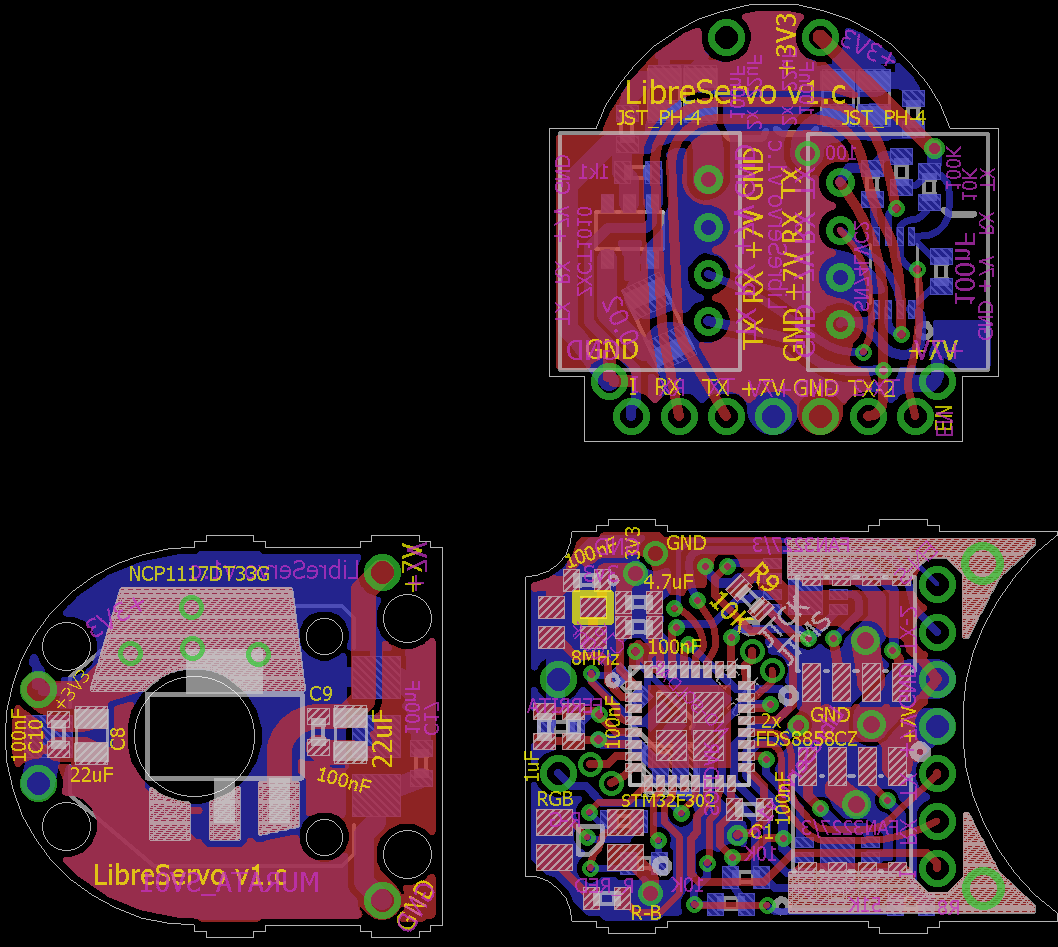
Nuevo diseño y pedido de LibreServo [v1.c]

Tras un mes desde que detecté el error, cómo corre el tiempo..., ¡ya tengo una nueva versión de LibreServo y ya están fabricándose en JLCPCB!.
Ahora mismo ando con muy poco tiempo, pero la tardanza no sólo ha sido por mi poco tiempo, también he decidido introducir varios cambios y mejoras:

  • Cambiar tamaño y limpieza de textos
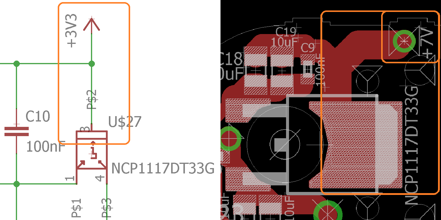
  • Cambiar encapsulado del regulador lineal
  • Cambiar condensadores y resistencias para que no entorpezcan
  • Modificar el valor de las resistencias del led RGB
  • Poner agujeros pasantes para un futuro encóder
  • Modificar footprint de varias resistencias y condensadores para optimizar el espacio
  • Modificar pistas serie para que sean curvas
  • Modificar cableado conectores (orden al revés)
  • Mover el gateMosfet para que no coincida con el conector
  • Agrandar footprints de los gateMosfet y del microcontrolador
  • Generar dos pines de alimentación
  • Añadir normbre y versión a la placa
LibreServo v1.c
LibreServo v1.c

Error in LibreServo v1b

With the website finished, I finally had time to continue programming and testing my LibreServo, but the joy was short-lived.

After soldering the three PCBs together, I proceed to power the LibreServo for the first time from a battery instead of the ST-link programmer ... and a white smoke preceded by sparks made an appearance. The STM32F302 microcontroller has been completely blown up, and there is a huge short between ground and the 3.3V line. After looking closely, I see that there are tin chips between the legs of my microcontroller, right between vdd and vss! Is it possible that when welding the three PCBs I was not careful enough and some "chips" has ended up where it should not?

Design error
Error en el diseño de LibreServo v1b

Desingns, schematics and PCB

After detecting the error in the design in the serial communication part as I commented in the rush, that bad advisor, I had to update the designs and therefore the designs previously shared here and here are outdated. As this could happen more times in the future, and as I also want to share the files themselves, I leave in this post the latest edition of the designs in photo and in Github I will leave the uploaded files also. Of the PCB layout file, there are 4 versions. Versions a, b and c correspond to the special versions that I had manufactured as I mentioned and explained in the entry of my first LibreServo order.

Schematics and designs
Buses

Diseños, esquemas

Sin poder entrar en todos los detalles y decisiones tomadas, en el propio diseño electrónico y esquemático, se ha seguido siempre el propio datasheet de los componentes seleccionados, en algún caso aumentando los condensadores de desacoplo. Dejo a continuación el esquema general completo (se ha corregido a posteriori algún detalle), y comentaré las partes en los que ha habido algún pequeño cálculo.

Primer diseño esquemático de LibreServo
LibreServo sch