These schematics will not last long because new changes have already been made and will be sent to manufacture in the coming days if all goes well. The order of the next version will coincide with the Chinese vacations, but I hope not to have any problem except some small delay already announced by the manufacturer JLCPCB.
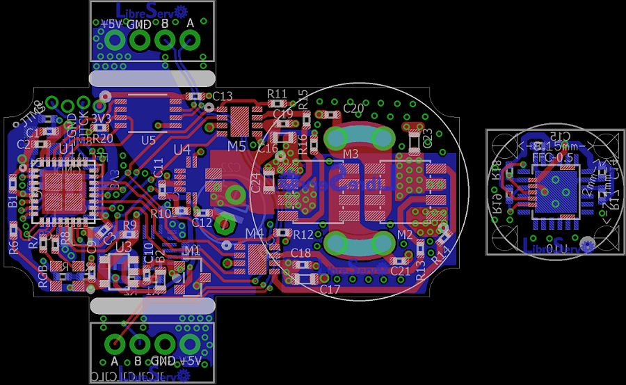
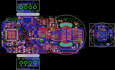
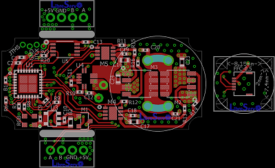
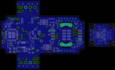
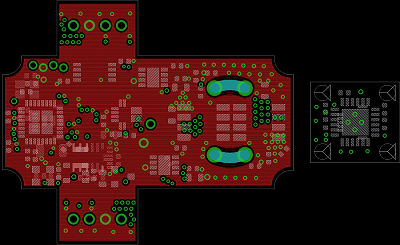
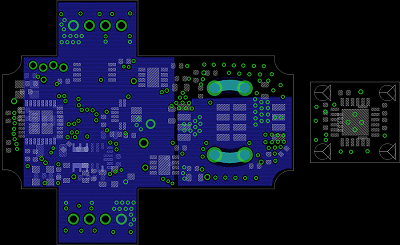
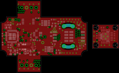
In this LibreServo version, the main PCB, goes from 4 to 6 layers because JLCPCB, as we mentioned in the article of changes in LibreServo v2.1, has made a very aggressive offer in which it is cheaper to manufacture a 6-layer PCB instead of 4, taking into account that in 6 layers you get for free the ENIG finish (in gold) and the vias are filled and covered, in other words, a totally professional finish. It is a really crazy offer.
Despite all this, of course LibreServo will maintain full compatibility with 4 layers and only when generating the gerbers the central layers are removed and the matter is solved.
In this version not many more major changes have been made, but they can be summarized as follows:
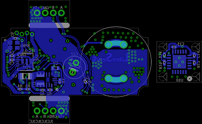
- Space has been given in the four corners to be able to reinforce the cover of the servomotor that has been designed in 3D. In the previous version I was limited by space and if the servomotor cover was screwed on tightly, it would crack in the screw area.
- We have tried to improve the routing of several components, use polygons where possible and improved the use of tracks.
- All the texts on the board have been tweaked.
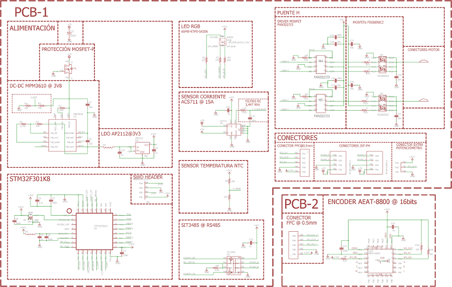
- The LibreServo schematic has been reworked to meet certain standards.
LibreServo v2.1 Schematic
LibreServo v2.1 PCB Gallery