LibreServo v2.3.1. Release Version
 LibreServo v2.3.1. Release Version
LibreServo has finally reached the first final Hardware release (version 2.3.1)!

It has been a long road and there is still a long road ahead, but now on the software side. LibreServo will not stop here and later on there will come new projects that make use of LibreServo, like a possible 3D biped robot, but all of that will come in the future and all of it will be announced here so let's stop the guessing and talk about the now.
 Production Files
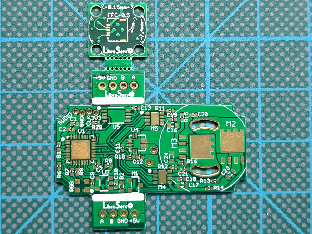
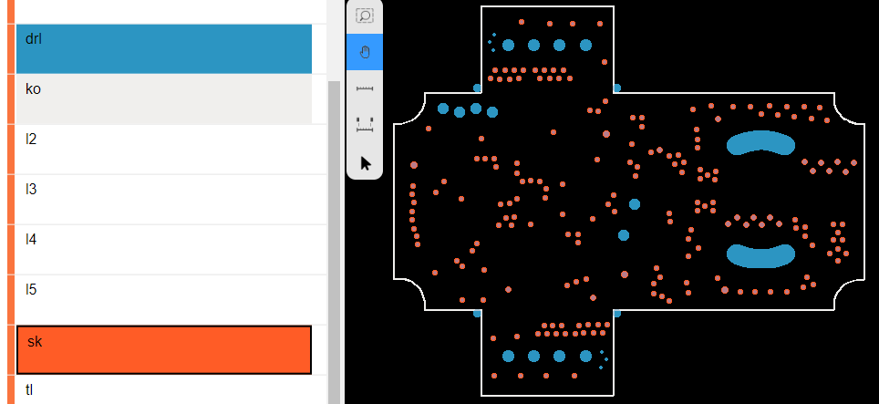
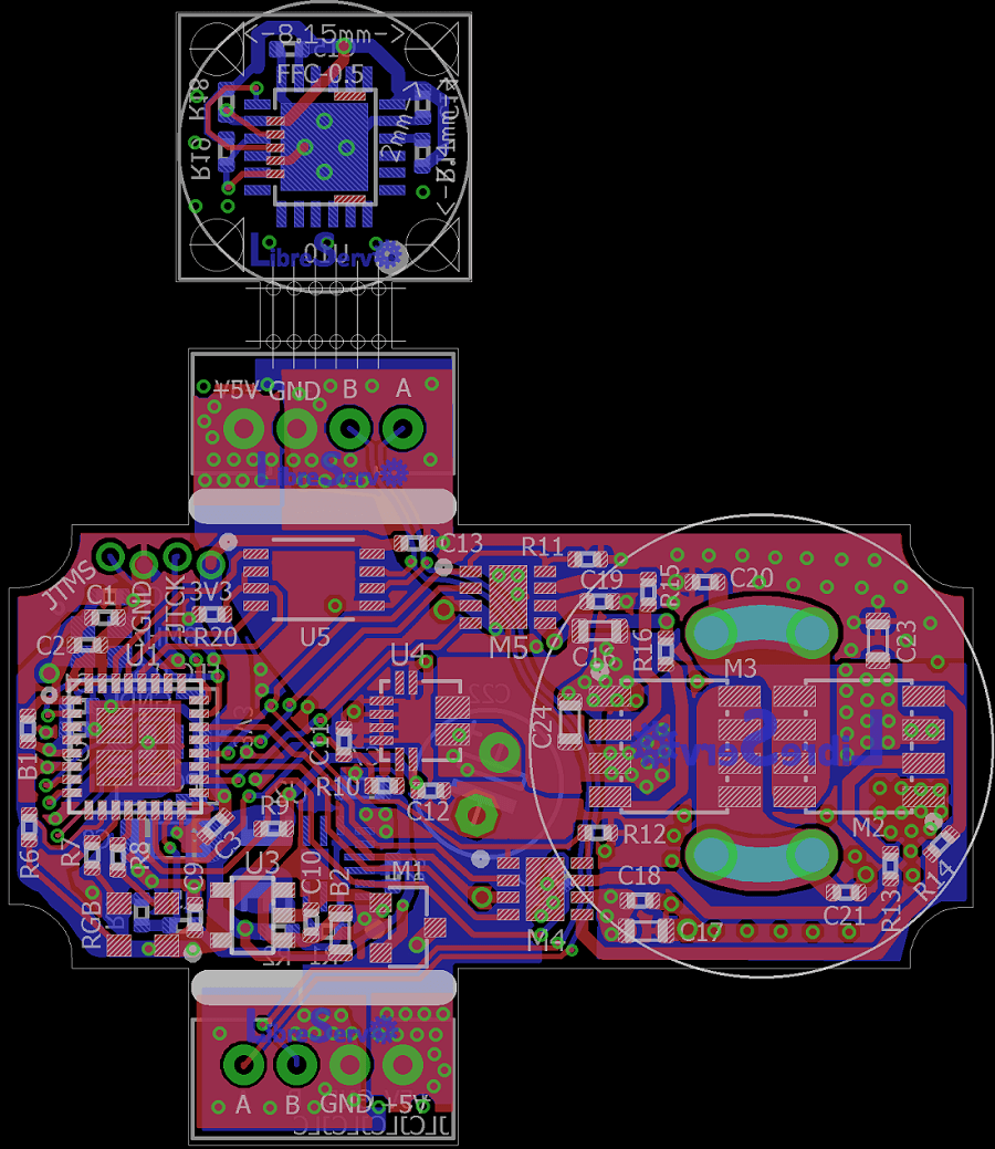
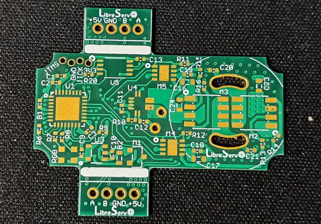
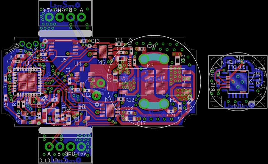
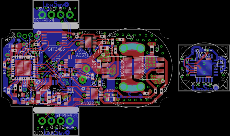
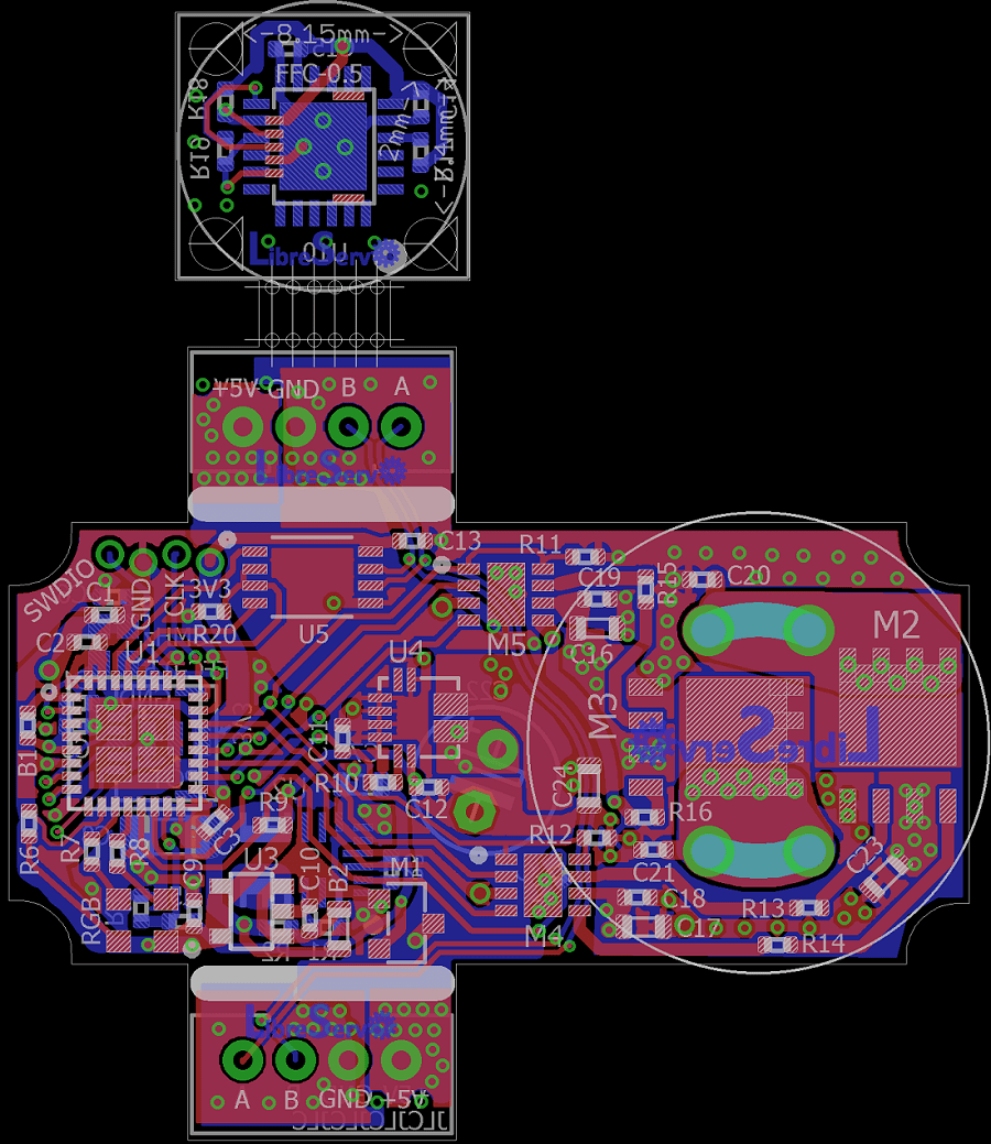 LibreServo v2.3 PCB
 LibreServo v2.2 PCB
 New LibreServo v2.1
 LibreServo v2.1 PCB
 LibreServo v2 PCB
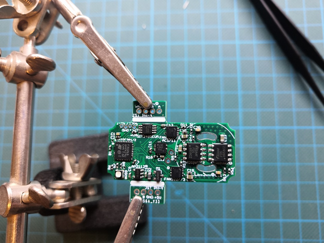 Soldering the first LibreServo v2