It has been a long time since my last update, a pandemic in between and many changes. Be that as it may, LibreServo continues moving forward, little by little, but it moves 💪.
During the previous versions of LibreServo I have continually encountered different problems in the design and without knowing exactly how different components were going to behave, in addition, later trying to debug the board being so compact and without extra space to be able to even solder a cable to be able to see the signs, always complicated everything too much.
That is why I have created a specific board to test all the components that LibreServo will carry and it is what it should have done from the first minute. With the board I want to try:
- ZXCT1010 current sensor with Zener Diode to avoid possible overvoltage.
- Use of a mosfet to protect LibreServo against a change in power polarity, for example the battery being connected the other way around.
- New ultra compact step-down mpm3610.
- Different filters based on ferrite beads to clean the step-down output.
- New ap2112 linear regulator.
- New NTC temperature sensor.
- New RGB Led more compact than in previous versions.
- New RS-485 chip and compare against RS-232 in electrical noise situations.
- New AEAT-8800 sensor, magnetic encoder.
- The full H-bridge.
- Test the feasibility of manufacturing vias in pads.
- Try to use mouse bites in the PCB, make small aligned holes to be able to have several designs on the same PCB and easily separate them.
- Text size tests.
- A long etcetera...
I had the board manufactured at jlcpcb and from the moment I had it manufactured until it arrived home (always with the cheapest postal delivery), it took only a week and a half! Quite a record, so as I write these lines, I already have the board in my possession and I am doing the first tests. Here is a peek:
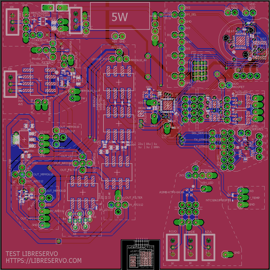
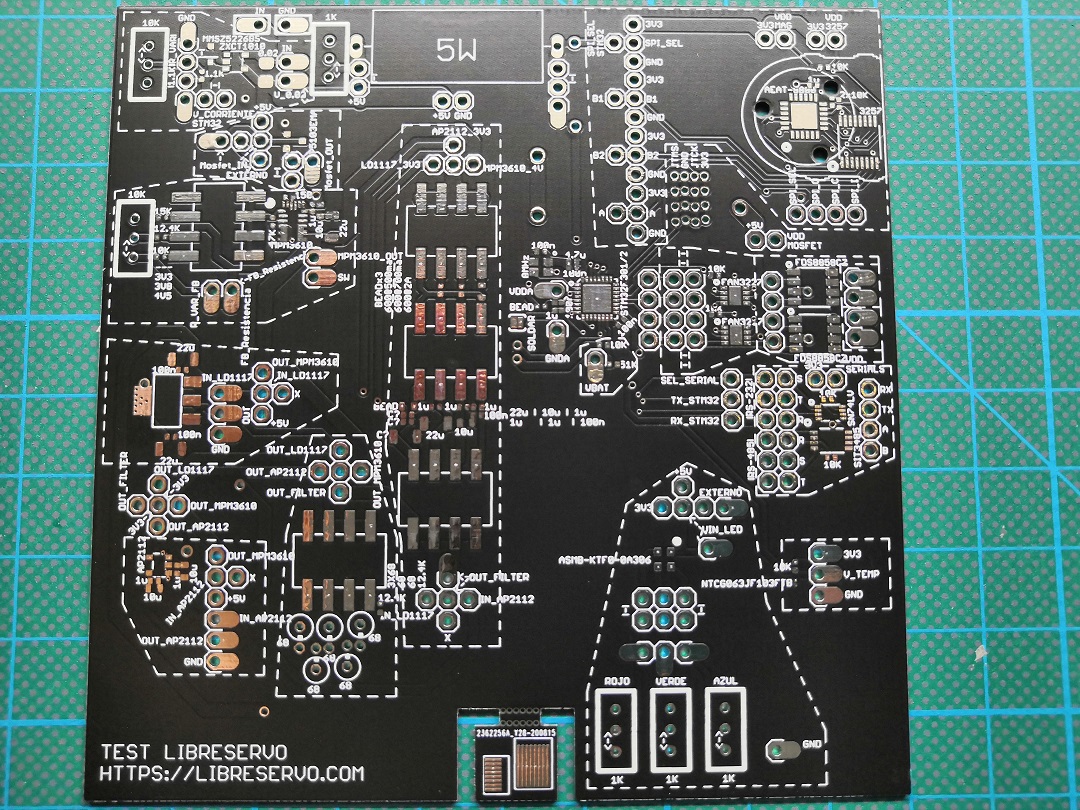
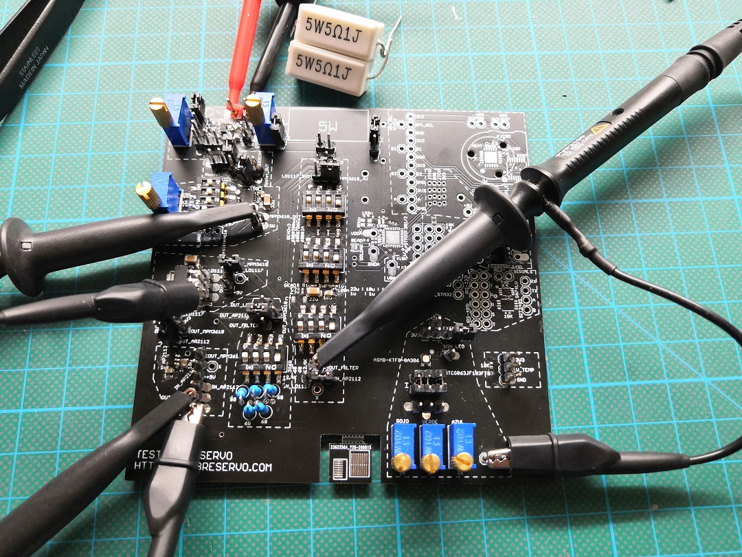
As you can see, there are lots of changes and new components that I want to test. I will be making small entries with the tests that I will be doing in the coming days.
This is a test PCB, but if someone wants the diagrams, let me know in the comments and I'll upload them 🙂.