After several tests, the LibreServo hardware is finally chosen and it's working, even the H-bridge that gave me a lot of problems! In general, all the parts of LibreServo remain as they were, because they were already working correctly, except the parts are discussed in this article.
H-BRIDGE
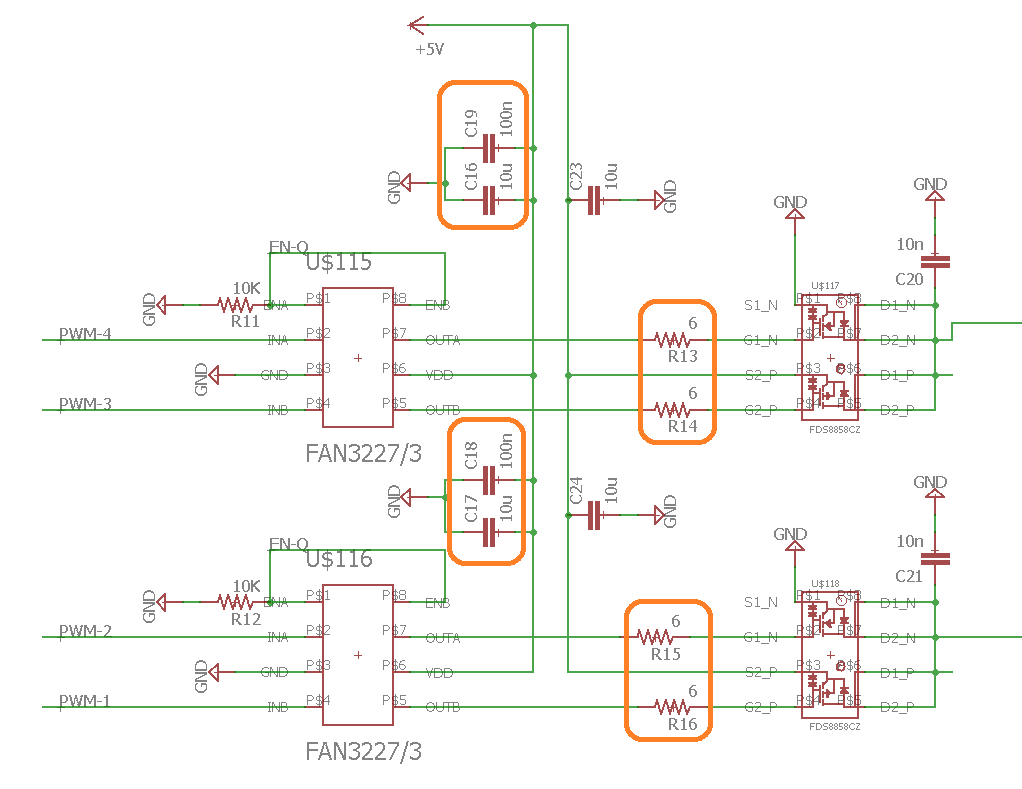
Let's go directly to the biggest problem I had, the H-bridge. The inclusion of the 6 Ohms resistors between the mosfet driver and the mosfet gates together with the 10 uF decoupling capacitors in the drivers, that I forgot to put on the first test PCB, were decisive.
The actual problem with the H-bridge was a set of several problems. On the one hand, by not having decoupling capacitors, the mosfet driver caused a lot of noise in the driver's own signal. In addition, by not having the 6 Ohms resistance in the lines between the driver and the mosfets, it caused more intense consumption peaks and in turn greater noise, all this caused the mosfets to be activated and deactivated producing more noise and everything went into a loop, burning the mosfet drivers.
With the current configuration it works without problems with a PWM of even 140 KHz and several amps in continuous in all the range of use of LibreServo, from 4.5 to 18 Volts.
H-bridge scheme
CURRENT SENSOR
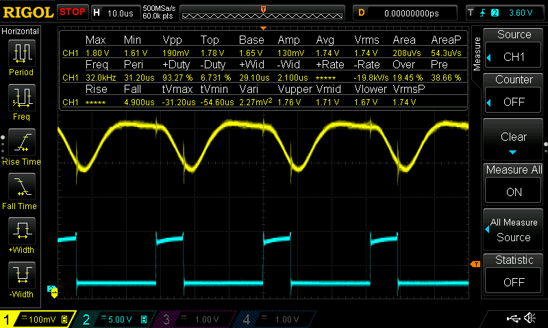
I had to dedicate more time than expected to this section that seems simple. The problem that there was and that was seen thanks to the oscilloscope (I will never stop recommending having one if you want to do some minimally serious project), is that the sensor is too fast and you could see the motor's PWM at 32KHz perfectly in the output of the sensor. With an RC filter at 1KHz the signal was cleaned a lot, but it required that any torque control that you wanted to do should be at 1KHz at most (even less). Since the torque control should go faster than the normal position PID loop (about 10 times faster), this did not help us.
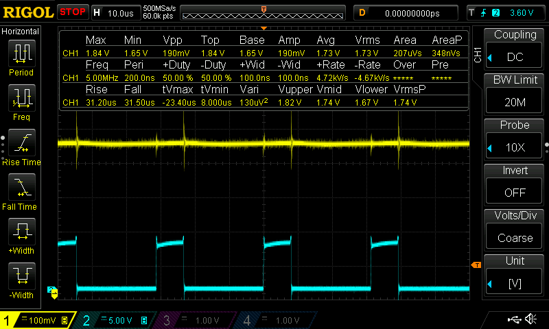
The final solution was to raise the PWM frequency to 140KHz, and then apply an RC filter to 10KHz. This causes the microcontroller to only have 9 bits of resolution, since 140,000 * 512 = 72,000,000 which is the frequency of the microcontroller. To solve this new problem, a dithering technique will be programmed to enhancement the resolution of the PWM to 12 bits. I will make a small article about it.
With all this, the current sensor is now ready to work in perfect condition.
ENCODER
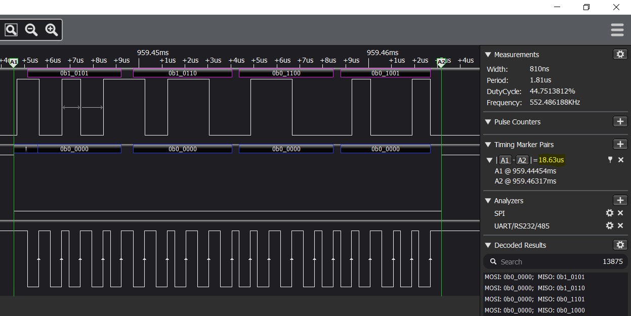
Finally, the sensor reading code was optimized to drop below 19uS in the reading, dropping from 25.2uS to 18.XX. I am more than happy about it.
Fast AEAT8800 SSI reading
LibreServo sending data via RS485 to Arduino plotter
Finally, the new version of LibreServo is on its way home! 🤩