After analyzing all the parts of LibreServo, I have decided to make several design changes again. I am happy with the results obtained with the test board since without it, it would have been impossible to analyze all the components separately and detect all the errors and faults that I have found, it is something that I should have done from the beginning and it would have saved me a lot of time. The conclusions are as follows:
Current Sensor
As we saw in the analysis of the ZXCT1010 sensor, I will not continue using that sensor, as a substitute I will use the 15A ACS711KE. A sensor that measures current in both directions, that I can easily protect against reverse voltage and that ensures me that in current peaks, whatever happens, the sensor will never generate a voltage higher than the one supported by the microcontroller.
Protection against change of power polarity
It is not unreasonable to think that when working with batteries, connectors... in some carelessness we could end up with the battery connected the other way around, it has happened to all of us. In a normal circuit without protection and working with LIPO batteries that can give dozens of amps effortless, that means that carelessness will mean burning one or more components instantly, microcontroller, sensors, drivers... Even the PCB's tracks themselves I've seen it melt and destroyed in less than a second when connecting a battery backwards.
A simple but effective way to protect a circuit against a change in power polarity is to use a P mosfet. In our case I have chosen the P5103EMA, due to its small size, due to its low RDS(ON) of less than 0.05 Ohms in normal conditions and for supporting reverse voltage up to 20V. In the different tests that I have carried out, it has behaved as expected without presenting any problem.
Polarity change protection with Mosfet P
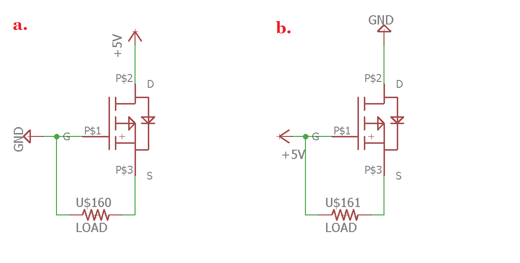
In case a) VGS is negative so the transistor is activated and works as a closed switch, while in case b) VGS is positive so the mosfet transistor works as an open switch and bloks the current protecting the rest of the circuit.
New power supply, mpm3610 + ap2112
After the extensive analysis of the mpm3610 that I did, the final power supply circuit will consist of a 3.8V mpm3610 followed by a 2A ferrite that will filter the signal before the AP2112 which will give us the final 3.3 volts.
NTC temperature sensor
The temperature sensor gave no problem and worked as expected. I tested it in various temperature conditions between 5 degrees in the refrigerator and 80 degrees with the air soldering iron and the response was always quick and very close to reality. The only complex thing was the programming part, which once I found the right formula was not a major problem:
if(dma_adc1_buff[1]==2048) external_temp_A = 2047*3.3/4096;	//Volt=lectura*3.3V*4096 (Evitar en la fórmula log(1)=0 y X/0 es indeterminación)
else external_temp_A = dma_adc1_buff[1]*3.3/4096;		//Volt=lectura*3.3V*4096

external_temp_B = 3.3-external_temp_A;				//Caida_Volt=3.3-Volt
external_temp_B = external_temp_B/10000;			//Corriente=Caida_Volt/10KOhms
external_temp = external_temp_A/external_temp_B;		//R2=Volt/Corriente
external_temp_A = 3435/log(10000/external_temp);		//Fórmula cálculo de Temp en NTC
external_temp = ((25+273.15)*external_temp_A)/(external_temp_A-(25+273.15))-273.15;
New more compact RGB led
The new RGB led is much more compact than the previous version and its brightness is still totally remarkable. The new led ASMB-KTF0-0A306 reduces its size from 3.2x2.8 mm to 2.2x2 mm. I do not have a colorimeter, but by eye, white is achieved with the following resistors:
- Red Led: 187 Ohms (3,37mA)
- Green Led: 270 Ohms (2.23mA)
RS-232 vs RS-485 serial communication
Tests have been carried out and in both cases they have reached 9 Mbps without any problem, even trying to put electrical noise with an external motor. The problem is that although with two cables with RS-232 you could have full-duplex communication, manufacturers like Robotis that manufacture servos with RS-232 and RS-485 recommend using RS-485 over RS-232 almost in any circumstance, and Lynxmotion, which I analyzed a while ago, only offer RS-232 at 115200 bps despite the fact that the microcontroller they use has a much faster UART because, as they confessed to me, it was impossible for them to maintain higher speeds without introducing continuous errors in the communication.
RS485 Hello world at 9 Mbps
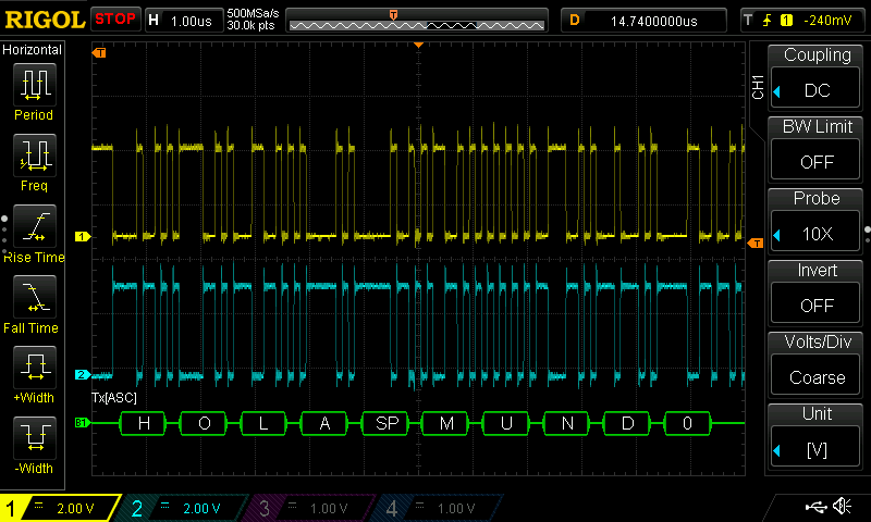
In addition, the use of error detection code was analyzed. After several tests, the correct operation of the error detection code was programmed and verified. Because it is a light code in terms of CPU usage and because there are only two extra bytes (16 bits) in communication, I have decided that LibreServo will use CRC16 (it can be disabled if the user wants it). CRC8 may fall short in transmissions of more than 64 bytes and CRC32 involves a lot of CPU use and is using sledgehammers to crack nuts in our case.
New AEAT-8800 magnetic sensor
At the beginning in the tests everything started badly with the sensor. I wanted to read the AEAT-8800 sensor through its standard encoder output (ABI) and thus be able to read it with the microcontroller's DMA automatically without using CPU cycles. Unfortunately, the sensor is factory configured with the lowest possible resolution in its ABI output and it must be changed using SPI to modified some registers. To make things more complicated, I did not have enough pins on the microcontroller for all of this, so I used a multiplexer to be able with the same pins on the microcontroller, to write the register using SPI and then change to read the encoder continuously. Unfortunately the change of pins in the multiplexer was not as fine as required and the sensor refused to write the register. I was going to give up until I discovered that by default the sensor is configured to work at maximum precision, 16 bits no more and no less 😍, if the position is read directly in SSI (a protocol very similar to SPI). So I removed the multiplexer, soldered several tracks, programmed the SSI protocol by hand and... the result was the following:
AEAT-8800 reading by SSI
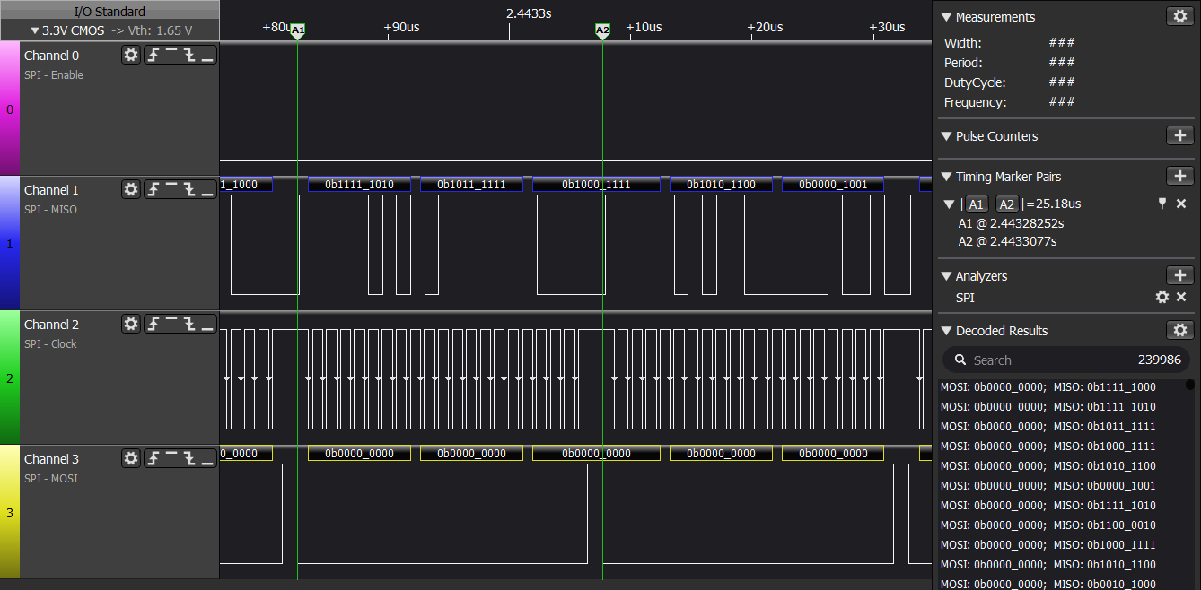
Even without optimizing the code, the sensor was read in 25.18µs which is roughly 40KHz. It will only be required to read the sensor at a maximum of 1KHz, which leaves enough room for the rest of the tasks and even optimizing my code a little it would not be difficult to go below 20µs, so I am very happy with the final result. Yes, it is true that I will not be able to read it through DMA, but I don't have to use a multiplexer, I read it at 16 bits of resolution instead of 14 that it gives in the ABI output and I also get 3 status bits in each reading that tell me if there is some error with the sensor.
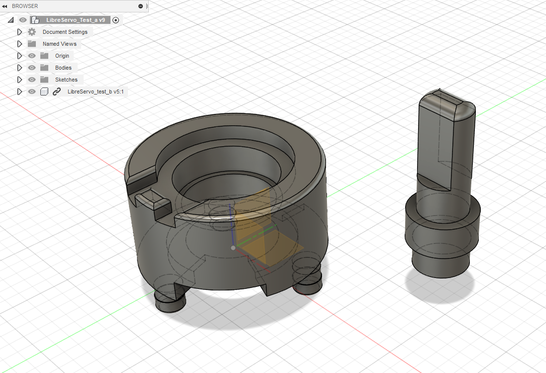
I also designed in Fusion360 the adapter for the sensor to replace the potentiometer of the servo motor. Once printed in 3D, it was perfect and fits without any problem in the same hole that the potentiometer used, with bearing and magnet included.
Encoder to potentiometer adapter
H bridge
A failure 😭. Without doubting, the H-bridge has performed fatally. On the one hand, the connection with the microcontroller was incorrect, but overcoming that obstacle, something happens between the mosfet driver and the P-channel mosfet that somehow turns on and off the P-channel mosfet and it enters in a diabolical loop oscillating in megahertz which ends up burning the mosfet driver in seconds ... The only explanation I have been able to find is that by using mosfets for the H-bridge with high capacitance on the gate pins, these work as little capacitors that resonate between the mosfet driver and the mosfet itself and ends up burning the driver. In principle, this problem is solved with a 6 Ohm resistance between the driver and the mosfet, but that is assuming that this was really the problem. Right now, it is the only unknown in the LibreServo project.
Next PCB
I am currently designing a new PCB with all the new changes. In principle, it will be a more definitive board than the previous test one, without so many options and switches and closer to the final design, but still with a marked test spirit to test and read the signals comfortably in order to find possible errors, especially on the H-bridge part. Also, it will be a 4-layer PCB as LibreServo will go from a 2-layer to a 4-layer design. Today JLCPCB is offering 5x5cm PCBs for just 2$! The change to 4 layers should relieve the PCB design in terms of space, improve the routing, have exclusive power and ground planes that will provide cleaner power and less overall noise... There really are not many excuses not to use the service of 4 layers in small PCBs, such as LibreServo.