Results and conclusions of the tests
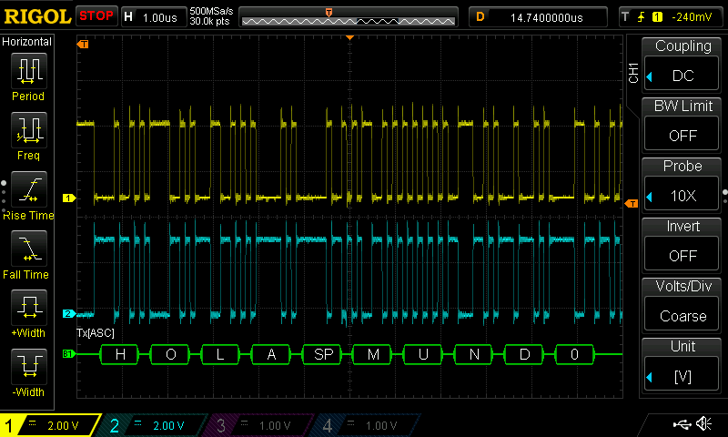
RS485 Hello World at 9 Mbps
After analyzing all the parts of LibreServo, I have decided to make several design changes again. I am happy with the results obtained with the test board since without it, it would have been impossible to analyze all the components separately and detect all the errors and faults that I have found, it is something that I should have done from the beginning and it would have saved me a lot of time. The topics to be discussed are:
- Current Sensor
- Protection against change of power polarity
- New power supply, mpm3610 + ap2112
- NTC temperature sensor
- New more compact RGB led
- RS-232 vs RS-485 serial communication
- New AEAT-8800 magnetic sensor
- H bridge
- Next PCB (4 layers)
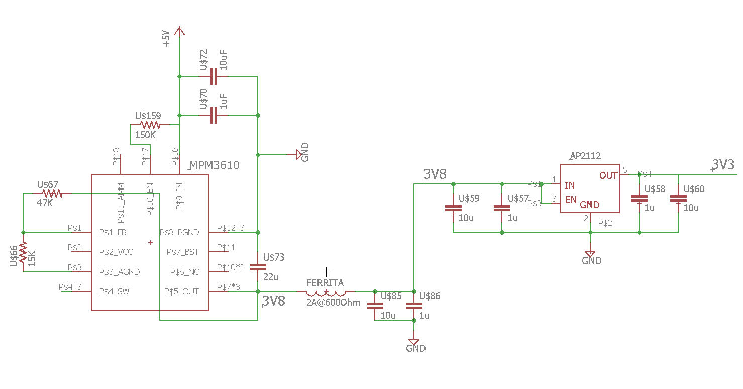 MPM3610 and AP2112 circuit
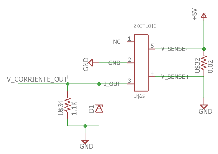 Circuito básico ZXCT1010 con protección Zener