Github

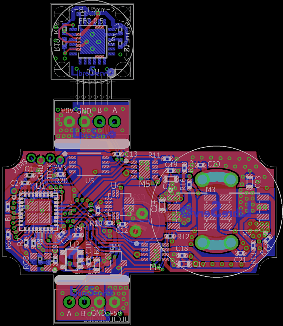
LibreServo v2.3.1. Release Version
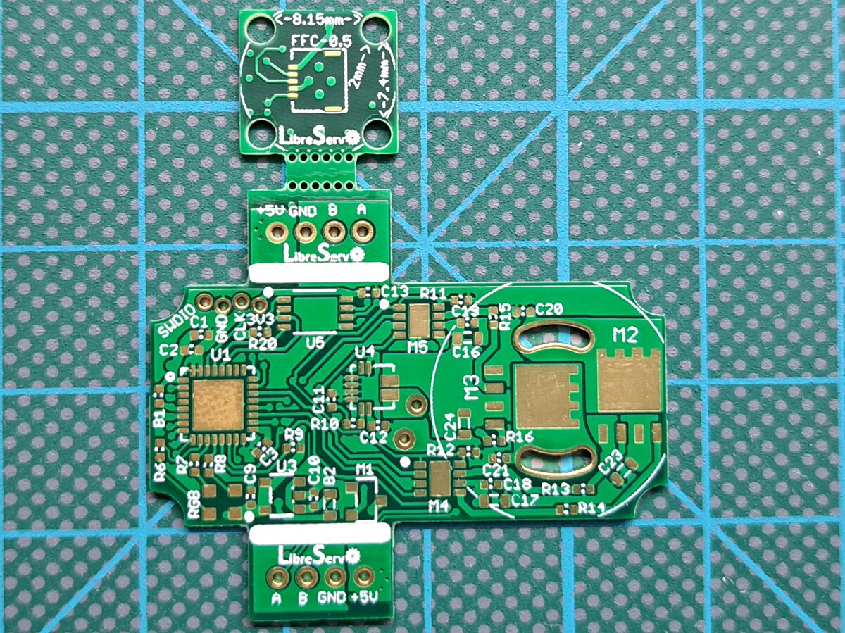
LibreServo v2.3.1 Servo hack LibreServo v2.3.1. Release Version

LibreServo has finally reached the first final Hardware release (version 2.3.1)!

party


It has been a long road and there is still a long road ahead, but now on the software side. LibreServo will not stop here and later on there will come new projects that make use of LibreServo, like a possible 3D biped robot, but all of that will come in the future and all of it will be announced here so let's stop the guessing and talk about the now.

LibreServo v2.3 schematics. Candidate version

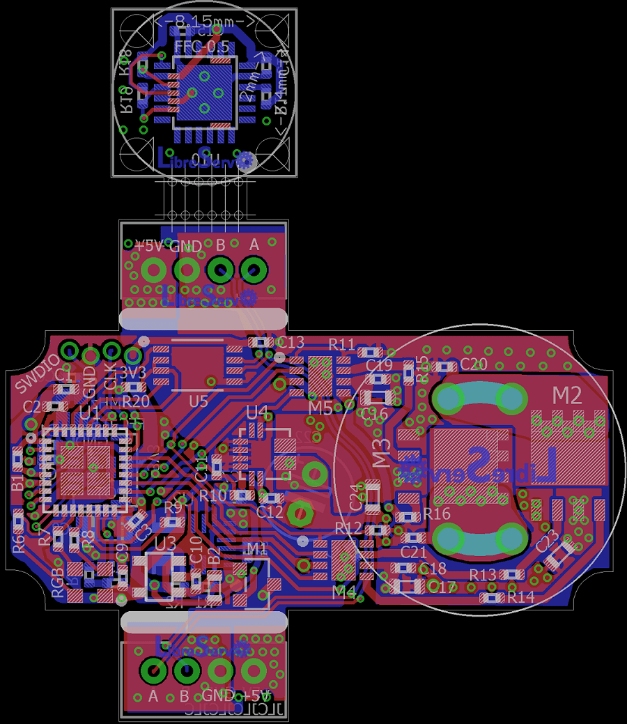
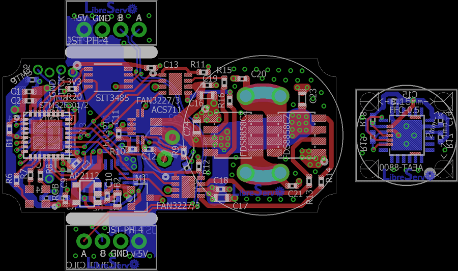
LibreServo v2.3 PCB servo hack LibreServo v2.3 PCB

A few days ago I presented LibreServo version 2.2 and announced that I had one last final change... this time the wait has not been long and I bring the new version of LibreServo, version 2.3.
This version should already be the final hardware version of LibreServo .
The biggest change that LibreServo has had in this latest version with respect to the previous one is the H-bridge. Risky move seeing what it cost me to make it work but I think it will be a remarkable improvement and the missing component to make LibreServo the definitive option.

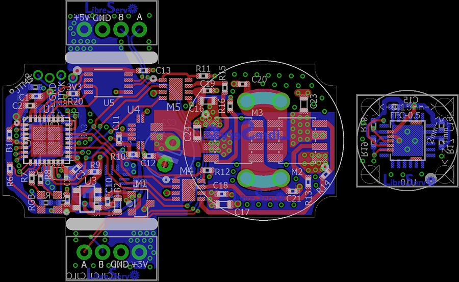
LibreServo v2.2. Pre-Release version?

LibreServo v2.2 PCB servo hack LibreServo v2.2 PCB

Pre-final version. This was going to be the final version, was going to be, because in the end it is not going to be.

  • The oscillator has been changed for a more compact one.
  • The position of several components has been slightly reworked
  • Ground planes have been generated on the outer layers
  • The position of the silk-screen printing has been repositioned with the idea that the vias will be capped and it will be possible to silkscreen on top of them
  • The PCB has been narrowed by a few tenths of a millimeter to fit perfectly to the servomotors
  • The two PCBs have been joined by using mouse-bites

In general, they are all small changes, but... just before placing the order I went back to review each and every one of the components, and there is one that I have decided to change and it is a very important one that has been in LibreServo from the beginning. In the next article I will unveil the final change 😉

LibreServo v2.1 Schematics

LibreServo v2.1 PCB LibreServo v2.1 PCB
These schematics will not last long because new changes have already been made and will be sent to manufacture in the coming days if all goes well. The order of the next version will coincide with the Chinese vacations, but I hope not to have any problem except some small delay already announced by the manufacturer JLCPCB.

In this LibreServo version, the main PCB, goes from 4 to 6 layers because JLCPCB, as we mentioned in the article of changes in LibreServo v2.1, has made a very aggressive offer in which it is cheaper to manufacture a 6-layer PCB instead of 4, taking into account that in 6 layers you get for free the ENIG finish (in gold) and the vias are filled and covered, in other words, a totally professional finish. It is a really crazy offer.

Despite all this, of course LibreServo will maintain full compatibility with 4 layers and only when generating the gerbers the central layers are removed and the matter is solved.

LibreServo v2 Schematics

PCB para test LibreServo LibreServo v2 PCB

I had pending for months to upload the schematics to the web. The schematics are exactly the same with which I made the LibreServo v2 PCBs but with the texts corrected in position so they read better.

In previous posts as you can read in the article of the first LibreServo test board and in the conclusions of the second LibreServo test-board, the LibreServo changes were massive in each and every aspect. Virtually every component was overhauled and moved to a two PCB, four-layer design.

New version of the 3D encoder parts


LibreServo encoder assembly video

To know the position of the servomotor axis, LibreServo uses the AEAT-8800 16-bit encoder. This encoder replaces the potentiometer that the servomotors have and with it we get much more precision and allows the servomotor to rotate 360 degrees.

To achieve this, LibreServo makes use of a tiny 10.2x11.2 mm PCB to which a 3D printed part of the same size and shape as the original potentiometer is attached. This 3D printed part consists of 3 small parts, a 4x7x2mm bearing and a small 6x2.5mm diametrically magnetized magnet. Only a glue point is needed to fix the magnet. The rest of the parts, bearing and PCB are designed to be snap-fitted and fixed.

Updated LibreServo software (version v0.1)

After several months of work, LibreServo has finally reached version 0.1 in the software. What does this mean? It means that LibreServo is still in Beta version, but it is mature enough to present itself in society. This will be only the first of several entries that I will be uploading these days.

I have updated the Github of LibreServo with the latest files and I will try to keep it updated.

In the next few days I will upload the documentation of LibreServo commands, but in case anyone wants to read the code itself, I have made two small diagrams to help understand how LibreServo works.