We have a winner. Test results in PCB test 2


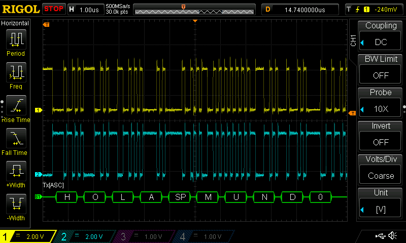
LibreServo sending data via RS485 to Arduino plotter

After several tests, the LibreServo hardware is finally chosen and it's working, even the H-bridge that gave me a lot of problems! In general, all the parts of LibreServo remain as they were, because they were already working correctly, except the parts are discussed in this article.

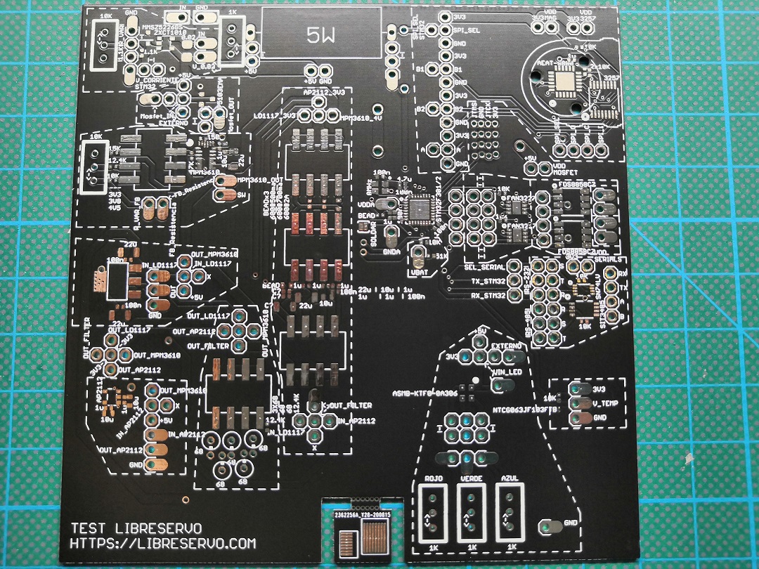
New PCB Test v2 for LibreServo


Hello World in LibreServo PCB test v2

A month ago I was analyzing the results and conclusions obtained with the LibreServo test PCB v1 and trying not to lose momentum this month I have designed, I have ordered new PCBs and I have already assembled the LibreServo test PCB v2! 🥳

It is the first PCB that I have designed with 4 layers for LibreServo and I hope that this will mitigates some issues with the H-bridge that I think comes, in part, from electronic noise. For the rest, it is a PCB with the final components, it is closer to the final design in which I have forced myself to put the components as close as possible to each other to see the real limit between what is designed and what can be easily welded without overcomplicating things, everything holds up on paper but then you have to bring it to reality.

Results and conclusions of the tests

RS-485 9 Mbps Hello World
RS485 Hello World at 9 Mbps

After analyzing all the parts of LibreServo, I have decided to make several design changes again. I am happy with the results obtained with the test board since without it, it would have been impossible to analyze all the components separately and detect all the errors and faults that I have found, it is something that I should have done from the beginning and it would have saved me a lot of time. The topics to be discussed are:

  • Current Sensor
  • Protection against change of power polarity
  • New power supply, mpm3610 + ap2112
  • NTC temperature sensor
  • New more compact RGB led
  • RS-232 vs RS-485 serial communication
  • New AEAT-8800 magnetic sensor
  • H bridge
  • Next PCB (4 layers)

Power Analysis (MPM3610 + Ferrite + AP2112)

MPM3610 and AP2112 circuit with Ferrite MPM3610 and AP2112 circuit

One of the parts that I have changed the most in LibreServo and thought about is the power supplies. In previous versions it was a linear regulator that I reduced in size, but the truth is that I was not at all comfortable since if LibreServo was powered with only 12V, the linear regulator should dissipate up to 1.74 Watts and in 16v 2.54 Watts... something that was really unreal that it could handled.

A few months ago I discovered the MPM3610, and this finally made it possible for me to design the power supply as I wanted. This tiny component is a powerful 1.2A step-down that supports up to 21V input and also has a built-in diode and coil! It is the latter that makes it perfect for my design, due to the reduced space used, being the only step-down that is manufactured that has an integrated coil and diode in the same package. The difference between using a step-down and a linear regulator is that a linear regulator from 3.3V to 12V gives an efficiency of 35%, while a step-down of 80% or higher, the rest is dissipated in heat, so one is much more prone to overheating than the other. The downside of using a step-down is that they are quite noisy and their output is not as clean as one from a linear regulator.

Análisis del sensor de corriente ZXCT1010

Circuito básico ZXCT1010 con protección Zener MMSZ5226BS Circuito básico ZXCT1010 con protección Zener

El primer componente que voy a analizar en mi nueva placa para testear LibreServo es el sensor de corriente ZXCT1010, el cual es una versión mejorada del sensor ZXCT1009. La mejora sobre todo es en la parte baja del sensor, cuando hay poca caída en Rsense, parte en la que quería estar ya que no quiero que se desperdicie tensión en Rsense. Además, aparejado al sensor de corriente está el diodo Zener MMSZ5226BS para evitar que la tensión de salida del sensor de corriente pueda superar los 3,3V y quemar el microcontrolador.

New PCB to test LibreServo

LibreServo test PCB LibreServo test PCB

It has been a long time since my last update, a pandemic in between and many changes. Be that as it may, LibreServo continues moving forward, little by little, but it moves 💪.

During the previous versions of LibreServo I have continually encountered different problems in the design and without knowing exactly how different components were going to behave, in addition, later trying to debug the board being so compact and without extra space to be able to even solder a cable to be able to see the signs, always complicated everything too much.

Compras y cambios de los últimos meses en LibreServo

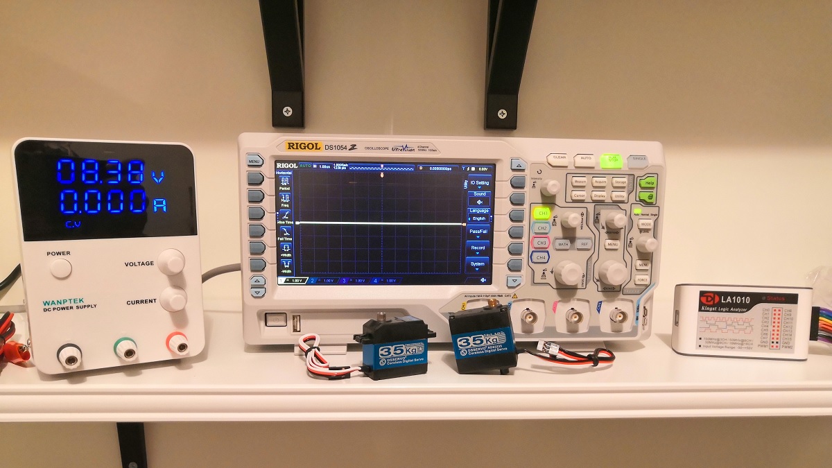
DS1054Z LA1010 GPS3010D DS3235 Nuevo material y herramientas para LibreServo

LibreServo va a sufrir varios cambios importantes y he decidido cambiar el método en el que estoy realizando las pruebas. Además, he decidido rascarme el bolsillo y comprarme algo más de equipamiento para medir todo lo necesario de una manera externa y precisa y así saber de antemano qué esperarme en LibreServo.

LibreServo cambia de Dominio

Domain change to Libreservo.com LibreServo changes to LibreServo.com

This last month and a half I have had several problems with my LibreServo.eu domain that have finally led to a change of domain.

Two months ago I received an email from my "domain manager" indicating that the auto-renewal had had a problem. Unfortunately this email went to spam and I didn't find out until I lost the domain and it was fallow for a month and a half. During that period they offered me to pay 100€ to recover it... but it seemed to me an abuse and I preferred to wait.

A month and a half later, the domain was finally released and could be bought again, but to my astonishment DomainProfi had gone ahead and stolen my domain! I talked to them and they told me that if I wanted my domain back I would have to pay, what a blatant theft! 🤬 So I decided to tell them to fuck off and change the domain to LibreServo.com, something I should have done from the very beginning a month and a half ago.

The change is not trivial, but after several hours of work, LibreServo is active again. Unfortunately, all the position it had achieved in Google has been lost and despite the fact that the .eu domain has not been working for months, Google continues to show results for that domain... I don't know how long it will take to forget the old domain and learn the new one. Be that as it may...


Long live LibreServo.com!

Manual primer proyecto STM32. Parte 4: Programar un microcontrolador STM32


Resultado final

En esta última parte vamos a grabar el programa Hola mundo para STM32 que vimos en la anterior parte en el microcontrolador.

Compilar "Hola Mundo"

Lo primero que tenemos que hacer es compilar el código pulsando el botón de Build All y asegurarnos que todo ha ido correcto, deberemos de ver el mensaje de Build Finished. 0 errors. Es posible que la primera vez que compilemos nos muestre unos warning de funciones que hemos definido pero que no hemos utilizado. No pasa nada, es completamente normal.

Uso de ST-LINK

Antes de seguir con la configuración voy a hacer un pequeño inciso y explicar el uso de los programadores ST-LINK v2. Como hemos visto en la primera parte de este tutorial, en la sección de SWD en STM32, vimos que tan sólo necesitaremos 4 pines, incluyendo alimentación, para programar un microcontrolador STM32 mediante SWD. Los dos programadores que utilizamos, tanto el ST-LINK v2 de la placa stm32f0discovery como el clon de ST-LINK v2, se conectan al ordenador mediante USB y son reconocidos automáticamente, en el caso que se muestra además, es el clon que se ha detectado perfectamente como un ST-LINK v2 original. En el clon los pines a utilizar son los que se muestra en la foto y no requiere de mayor configuración salvo actualizar el firmware como veremos más adelante. Para usar el ST-LINK de la placa stm32f0discovery sí que necesitamos de unas pequeñas modificaciones.

Manual primer proyecto STM32. Parte 3: Programación

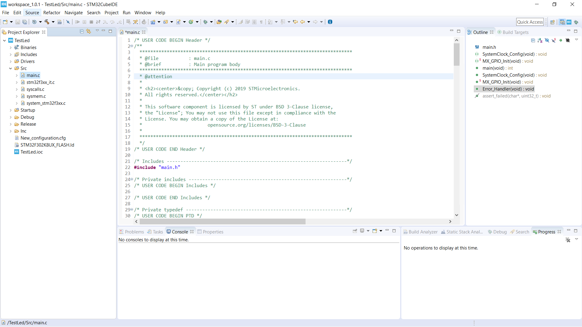
Código Base Código base recién creado

En éste paso, ya tendríamos que tener el código generado como hemos visto en IDE para STM32. El código se genera por defecto en src y Drivers de nuestro proyecto. Nuestro fichero principal es main.c que está dentro de src. Abrirlo y cambiar la perspectiva a C/C++. Veremos que en la nueva perspectiva, la interfaz ofrece un montón de ayudas y marcadores de texto que nos hará el trabajo mucho más productivo y fácil.

Antes de nada, nos tenemos que fijar en que CubeIDE nos genera a lo largo de todas las secciones, ficheros y librerías un montón de secciones encajadas entre títulos /* USER CODE BEGIN 0 */ y /* USER CODE END 0 */. Es en dichas secciones, y sólo en dichas secciones, donde programaremos. Si programamos fuera de dichas sencciones, CubeIDE no respetará nuestro código y lo borrará la próxima vez que regeneremos el código base, por ejemplo tras añadir una nueva interfaz o configurar nuevos pines. A veces, CubeIDE nos genera varias secciones seguidas de USER CODE en la misma sección y a la misma altura, es indiferente en cuál programemos, es sólo para nuestro orden. Se aconseja no borrar o modificar secciones de USER CODE independientemente de que no programemos en ellas.

Lo primero que siempre hago en todos mis programas es una serie de definiciones y añadir unas pequeñas funciones básicas que me ayudarán mucho a la hora de hacer los primeros programas y pruebas.

Subscription

Receive an email for each new article.

This question is for testing whether or not you are a human visitor and to prevent automated spam submissions.

2 + 2 =
Solve this simple math problem and enter the result. E.g. for 1+3, enter 4.