We have a winner. Test results in PCB test 2
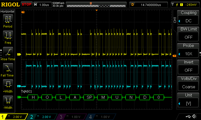
LibreServo sending data via RS485 to Arduino plotter
After several tests, the LibreServo hardware is finally chosen and it's working, even the H-bridge that gave me a lot of problems! In general, all the parts of LibreServo remain as they were, because they were already working correctly, except the parts are discussed in this article.
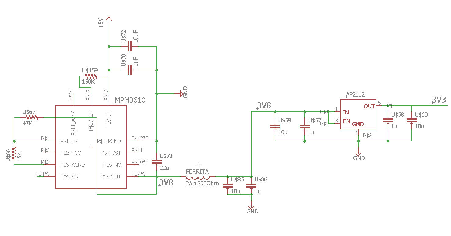 MPM3610 and AP2112 circuit
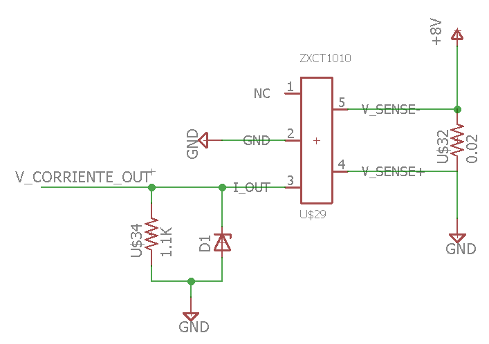 Circuito básico ZXCT1010 con protección Zener
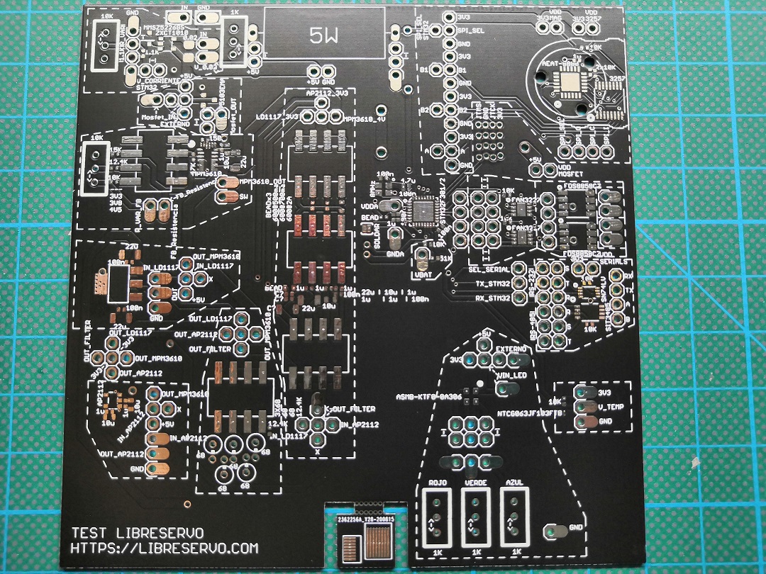 LibreServo test PCB
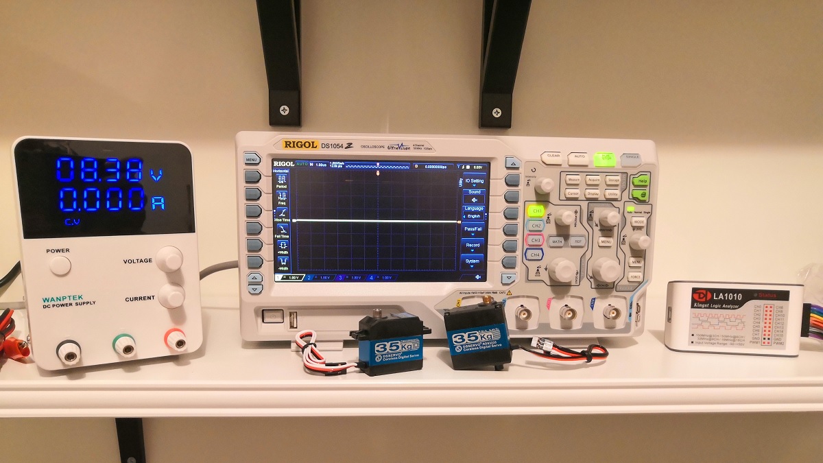 Nuevo material y herramientas para LibreServo
 LibreServo changes to
 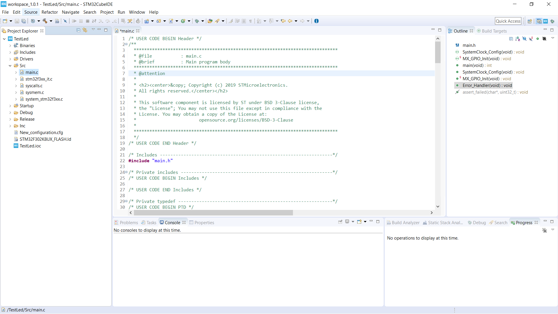 Código base recién creado