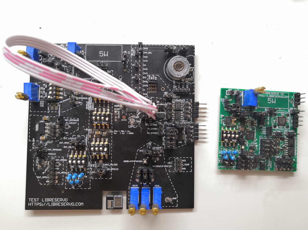
A month ago I was analyzing the results and conclusions obtained with the LibreServo test PCB v1 and trying not to lose momentum this month I have designed, I have ordered new PCBs and I have already assembled the LibreServo test PCB v2! 🥳
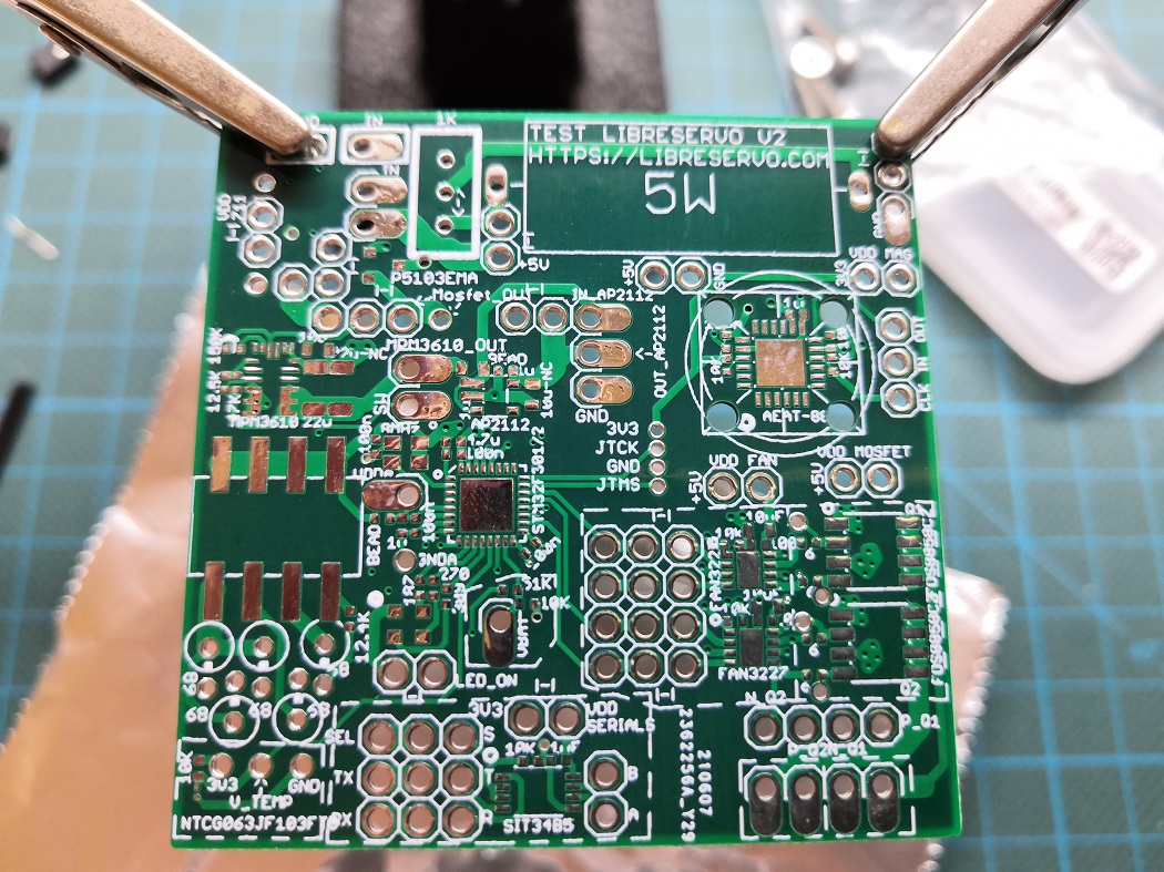
It is the first PCB that I have designed with 4 layers for LibreServo and I hope that this will mitigates some issues with the H-bridge that I think comes, in part, from electronic noise. For the rest, it is a PCB with the final components, it is closer to the final design in which I have forced myself to put the components as close as possible to each other to see the real limit between what is designed and what can be easily welded without overcomplicating things, everything holds up on paper but then you have to bring it to reality.
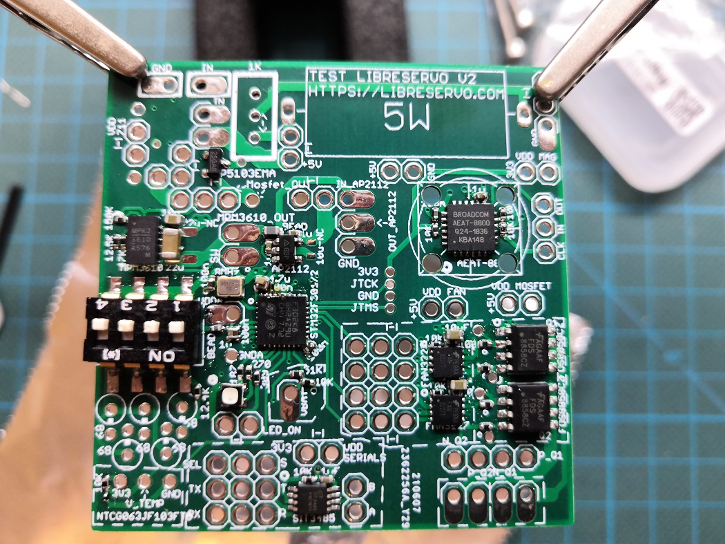
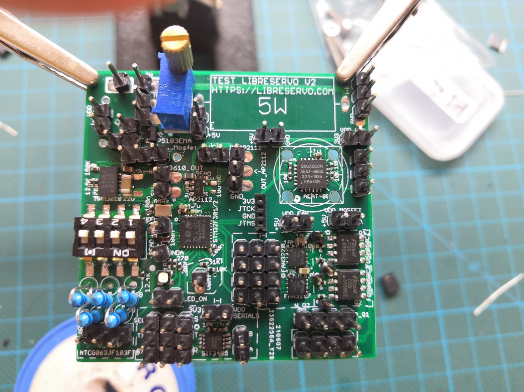
After soldering my first board, I couldn't be happier. I have verified certain limits that effectively make welding difficult, although they have not been a major problem in the final version I will leave more slack for the rest, the board has worked the first time with the test program where I test all the power supply, program the microcontroller and operate the RGB LED as Hello world. It remains to test the rest of the components, with special attention to the H-bridge, the only part that did not work on the previous test-board.