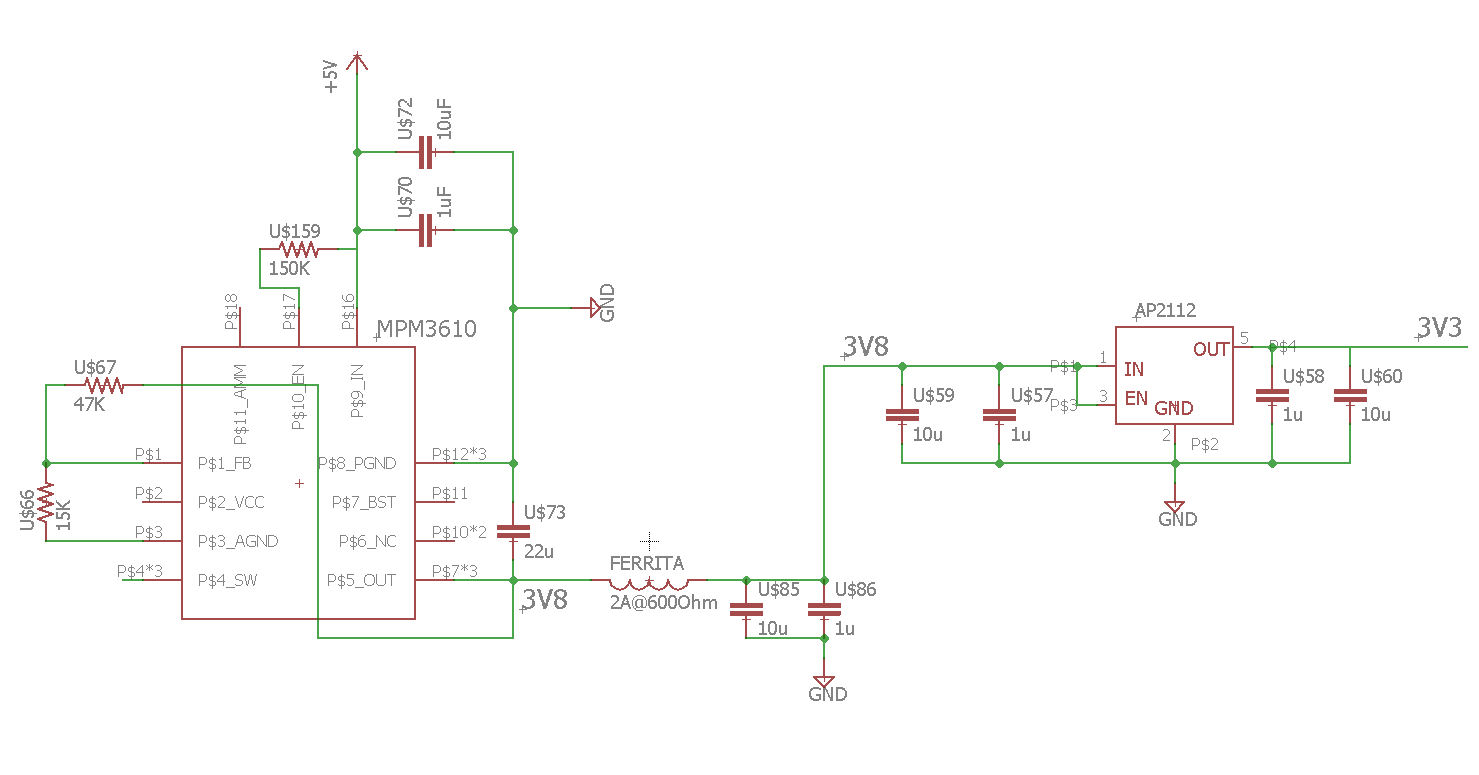
 MPM3610 and AP2112 circuit
One of the parts that I have changed the most in LibreServo and thought about is the power supplies. In previous versions it was a linear regulator that I reduced in size, but the truth is that I was not at all comfortable since if LibreServo was powered with only 12V, the linear regulator should dissipate up to 1.74 Watts and in 16v 2.54 Watts... something that was really unreal that it could handled.
A few months ago I discovered the MPM3610, and this finally made it possible for me to design the power supply as I wanted. This tiny component is a powerful 1.2A step-down that supports up to 21V input and also has a built-in diode and coil! It is the latter that makes it perfect for my design, due to the reduced space used, being the only step-down that is manufactured that has an integrated coil and diode in the same package. The difference between using a step-down and a linear regulator is that a linear regulator from 3.3V to 12V gives an efficiency of 35%, while a step-down of 80% or higher, the rest is dissipated in heat, so one is much more prone to overheating than the other. The downside of using a step-down is that they are quite noisy and their output is not as clean as one from a linear regulator.
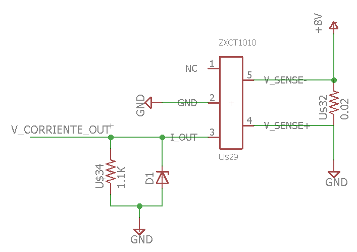 Circuito básico ZXCT1010 con protección Zener
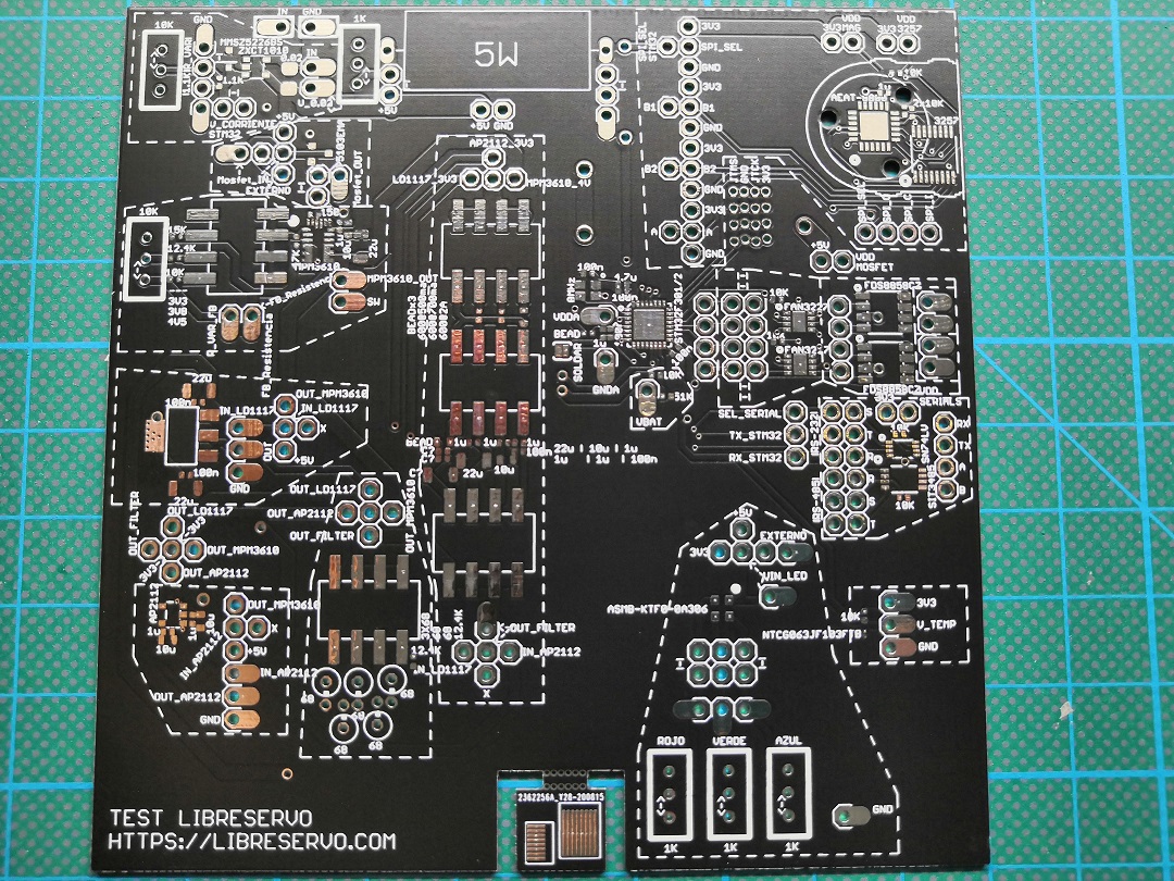 LibreServo test PCB
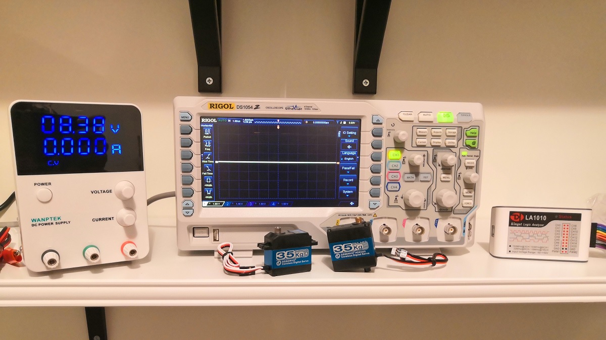 Nuevo material y herramientas para LibreServo