How to properly tune a PID
There are hundreds of guides on the Internet on how to adjust a PID and they can all be summarized in the following simple steps:
- Set KD and KI to zero and increase KP until the system corrects the error and starts oscillating. That would be the maximum KP
- Increase KD until the KP oscillation stops.
- Increase KI slightly so that the system fully corrects the error.
They seem like three simple and quick steps, but the reality is that in the end it becomes a sort of trying to guess the constants and after hundreds of tests and hours, if you are lucky, you get a relatively stable PID. It is a rather cumbersome task that rarely achieves a completely satisfactory result.
Let's forget about all that and try to obtain KP and KD mathematically.
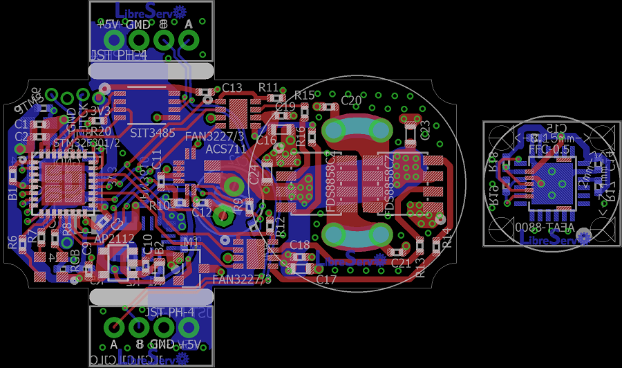 LibreServo v2 PCB
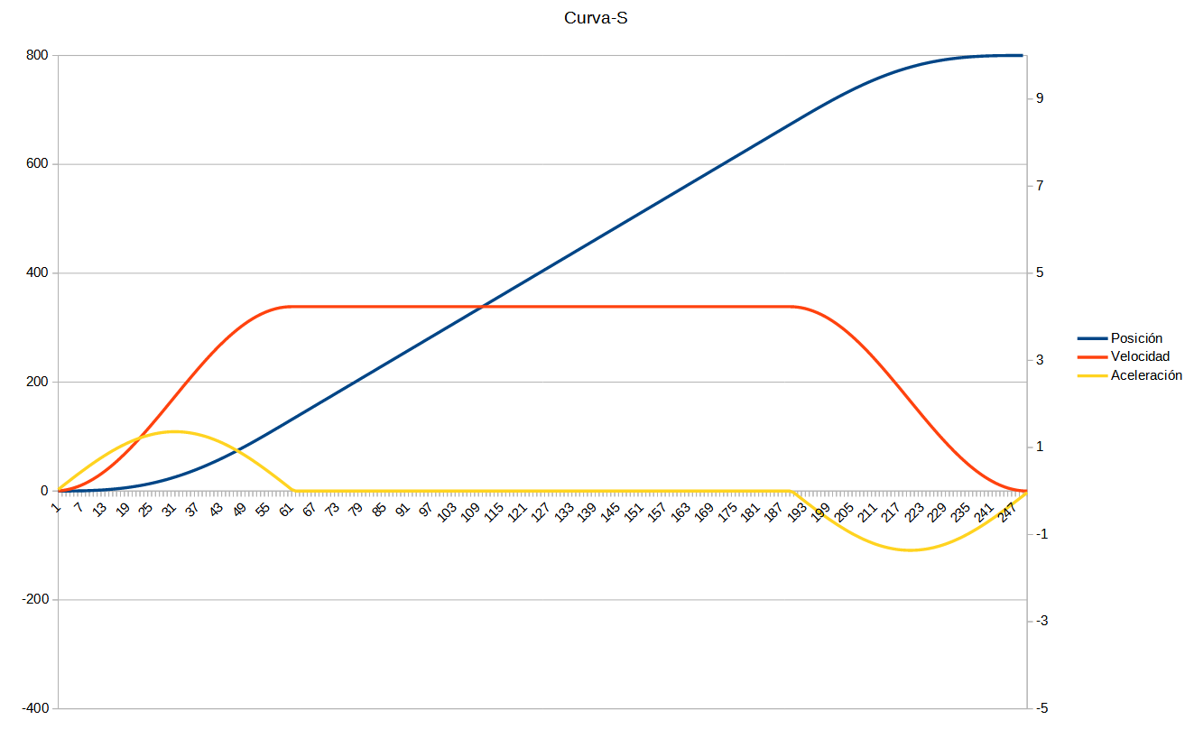 S-curve graph. Position, acceleration and velocity.

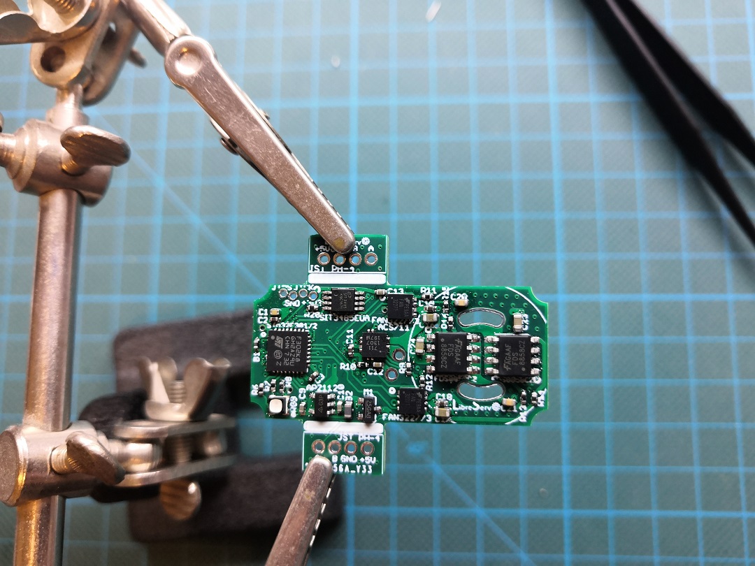 Soldering the first LibreServo v2