LibreServo v2 Schematics
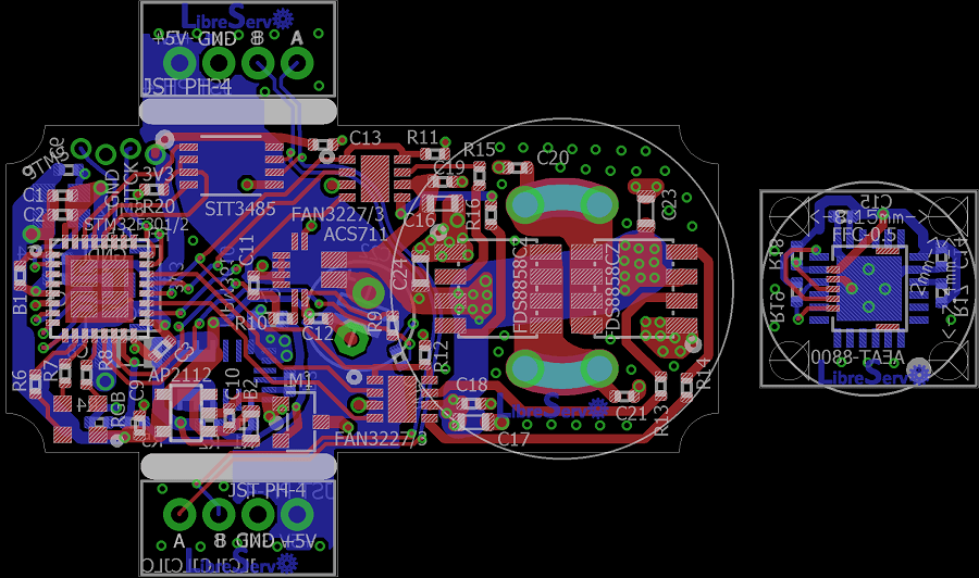 LibreServo v2 PCB
I had pending for months to upload the schematics to the web. The schematics are exactly the same with which I made the LibreServo v2 PCBs but with the texts corrected in position so they read better.
In previous posts as you can read in the article of the first LibreServo test board and in the conclusions of the second LibreServo test-board, the LibreServo changes were massive in each and every aspect. Virtually every component was overhauled and moved to a two PCB, four-layer design.
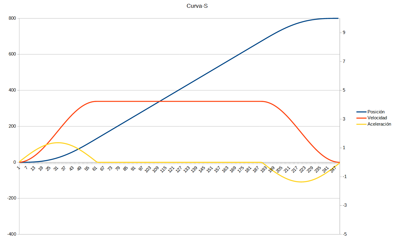 S-curve graph. Position, acceleration and velocity.
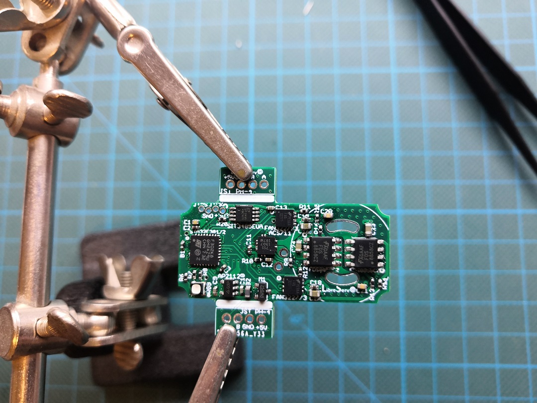 Soldering the first LibreServo v2